
Industrial Battery Engineering: How Chemistry, Safety, and Reliability Shape Modern Power Systems
When you select a battery for industrial equipment, the highest capacity or energy density does not automatically give you the most reliable solution. You must balance battery chemistry, electrical architecture, charging control, operating temperature, safety protection, cycle life, maintenance, and manufacturing consistency around the real demands of your application.
Consumer electronics are commonly designed around thinner devices, lower weight, faster charging, and longer runtime between charges. Industrial systems face a different set of priorities. A medical device may require stable output and complete production traceability. An industrial controller may depend on a battery for years of backup operation. A robot may need high peak current and frequent charging, while an energy-storage system must manage repeated cycles, temperature variation, and system-level safety.
Industrial battery engineering brings these requirements together. It examines how NiMH, lithium-ion, LiFePO4, lead-acid, and other chemistries behave under actual loads, charging conditions, temperatures, and maintenance schedules. It also considers factors beyond the cell itself, including cell matching, connectors, wiring, thermal sensors, protection components, testing, and repeatable pack assembly.
In this guide, you will see how chemistry defines a battery’s operating limits, why safety cannot depend on a BMS alone, how weak or mismatched cells affect an entire pack, and why testing and manufacturing quality ultimately determine whether a battery system performs predictably in the field.
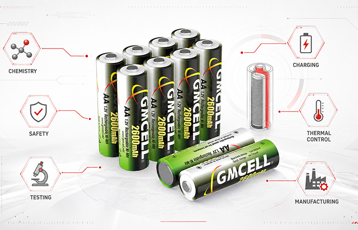
What Is Industrial Battery Engineering?
When you design or select a battery for industrial equipment, you are not simply choosing a cell with a suitable voltage and capacity. Industrial battery engineering combines electrochemistry, electrical design, thermal control, mechanical protection, charging strategy, testing, manufacturing, and lifecycle monitoring around the operating needs of your equipment.
Each discipline answers a different engineering question. Electrochemistry determines how the cell stores and releases energy. Electrical architecture determines how cells are connected and how the pack responds to continuous and peak loads. Thermal and mechanical design protect the battery from heat, vibration, shock, compression, and installation stress. Charging and protection systems keep the chemistry within its intended operating limits, while testing and manufacturing controls help ensure that a successful prototype can be reproduced consistently in volume production.
Electrochemistry
Defines cell voltage, energy density, self-discharge, temperature behavior, charging response, and aging mechanisms.
Electrical Design
Determines series and parallel configuration, pack voltage, capacity, peak-current capability, connectors, wiring, and protection components.
Thermal & Mechanical Design
Controls heat release, cell spacing, sensor placement, enclosure strength, and resistance to vibration, impact, and compression.
Charging & Protection
Matches the charger, cutoff logic, temperature limits, fuse, thermistor, or BMS to the specific battery chemistry.
Testing & Manufacturing
Verifies capacity, internal resistance, cycle life, environmental durability, assembly quality, and batch consistency.
The Core Goals of Industrial Battery Engineering
Before you compare battery chemistries, capacities, or cell formats, you need a clear set of engineering priorities. Industrial battery performance should be evaluated according to how consistently the system supports your equipment throughout its expected service life—not only according to a laboratory capacity result measured when the battery is new.
Reliability
You need stable voltage, predictable capacity retention, consistent cycling, dependable standby performance, and acceptable output across the real operating-temperature range.
Safety
Safety includes more than preventing fire. Your system should also manage overcharge, over-discharge, short circuits, excessive temperature, reverse polarity, leakage, and unexpected power loss.
Predictable Service Life
You should be able to estimate when the battery needs replacement, how capacity will decline, how often maintenance is required, and whether the pack will remain usable after long-term storage.
Application Compatibility
The battery must fit your equipment’s voltage window, peak-current demand, available space, charging method, environmental conditions, connector design, and maintenance strategy.
Total Lifecycle Cost
The lowest cell price may not provide the lowest total cost. You also need to consider replacement frequency, equipment downtime, maintenance labor, charging hardware, certification, transport, and disposal.
The best industrial battery is not necessarily the battery with the highest capacity or energy density. It is the battery that performs predictably within the real operating conditions of your equipment.
Battery Chemistry Defines the Operating Envelope
Your choice of battery chemistry establishes the basic operating limits of the entire power system. It affects the voltage available to your equipment, the amount of energy that can be stored, the current that can be delivered, the acceptable temperature range, the charging method, the protection architecture, and the maintenance your battery will require throughout its service life.
This collection of limits is often described as the battery’s operating envelope. A chemistry may perform well in one application but become inefficient, costly, or difficult to manage in another. You should therefore begin with the conditions inside your equipment rather than selecting a chemistry only because it offers the highest published capacity.
Nickel-Metal Hydride
NiMH is a mature rechargeable chemistry valued where you need stable operation, proven serviceability, and relatively straightforward pack protection. It can tolerate limited overcharge more readily than lithium-ion, although accurate charging termination and temperature monitoring are still essential.
For industrial controllers, medical equipment, emergency systems, and embedded devices that prioritize proven safety, stable discharge behavior, and long-term serviceability, a properly engineered NiMH Battery can remain a practical power solution.
Industrial controllers, medical instruments, emergency lighting, security systems, backup power, test equipment, and embedded electronics.
Trade-offs: lower energy density than lithium-ion, generally higher self-discharge, and strong dependence on cell matching and charging accuracy.
Lithium-Ion
Lithium-ion is often selected when your equipment requires high energy density, low self-discharge, reduced weight, or a compact battery enclosure. Its higher cell voltage also allows you to reach a target pack voltage with fewer cells.
Robotics, drones, mobile industrial terminals, portable medical devices, automation equipment, scanners, and power tools.
Engineering requirements: CC/CV charging, overcharge and over-discharge protection, temperature monitoring, BMS control, and cell balancing in multi-series packs.
Lithium Iron Phosphate
LiFePO4 is a lithium-ion chemistry frequently chosen where you need long cycle life, comparatively strong thermal stability, and dependable high-capacity operation. Its nominal cell voltage is typically around 3.2V.
Industrial storage, UPS systems, forklifts, electric equipment, lead-acid replacement packs, and large backup-power systems.
Trade-offs: lower energy density than some nickel-rich lithium-ion chemistries and continued need for appropriate BMS and charging control.
Lead-Acid
Lead-acid remains relevant where your project values low initial cost, established charging infrastructure, and strong starting-current capability more than low weight or compact size.
UPS systems, telecommunications backup, forklifts, starting systems, emergency power, and fixed standby installations.
Trade-offs: greater weight, limited deep-cycle performance in some designs, and cycle life that depends heavily on discharge depth and charging quality.
Where Solid-State Batteries Fit
Solid-state batteries may eventually offer improvements in energy density and safety by replacing some liquid electrolytes with solid materials. However, interface stability, manufacturing complexity, cost, scale, and commercial availability still need to be evaluated before they can be treated as a direct replacement for mature industrial chemistries.
| Chemistry | Energy Density | Safety Complexity | Serviceability | Typical Application | Charging Requirement |
|---|---|---|---|---|---|
| NiMH | Moderate | Moderate | High | Backup, medical, embedded systems | Constant current with voltage, temperature, and timer termination |
| Lithium-Ion | High | High | Moderate | Portable, robotics, high-energy devices | CC/CV with BMS and protection controls |
| LiFePO4 | Moderate to high | High | Moderate | Storage, UPS, industrial vehicles | CC/CV with chemistry-specific voltage limits |
| Lead-Acid | Low | Moderate | High | UPS, starting, fixed backup | Constant-voltage, float, and temperature-compensated charging |
Electrical Architecture Shapes Real-World Performance
Once you have selected a chemistry, you still need to translate individual cell characteristics into a battery pack that works with your equipment. The published capacity of a cell does not tell you whether the pack will remain above your device’s minimum voltage, support a motor-starting surge, or deliver stable power through connectors and wiring after years of use.
Nominal and Operating Voltage
Nominal voltage is only a reference value. The voltage your equipment actually sees changes with state of charge, current demand, temperature, and cell aging. You must confirm both the minimum startup voltage and the maximum voltage your electronics can tolerate.
Series and Parallel Configuration
Connecting cells in series increases pack voltage. Connecting matched cells in parallel increases capacity and current capability. Parallel construction does not automatically eliminate imbalance, so your design must still consider current sharing, cell matching, and charging behavior.
Continuous and Peak Current
Your battery must support both normal operation and short-duration current surges. A pack that delivers the required average current may still fail when a motor, pump, transmitter, relay, or heating element creates a temporary peak load.
Internal and Contact Resistance
Internal cell resistance, thin wires, undersized connectors, aging contacts, and poor welds all create voltage loss and heat. These losses become more visible as current rises and can reduce the usable capacity available to your device.
A battery may appear to have sufficient remaining capacity but still cause equipment shutdown if its voltage falls below the device threshold during a peak-current event.
Charging Strategy Is Part of the Battery System
You should not evaluate a rechargeable battery separately from the charger that supports it. Each chemistry responds differently to voltage, current, temperature, charge duration, and time spent at full charge. A charger that works well with one chemistry may damage another or cause your equipment to experience incomplete charging, excessive heat, accelerated capacity loss, or unsafe operating conditions.
A battery chemistry cannot be evaluated separately from the charging method used to support it.
NiMH Charging
NiMH cells are commonly charged with controlled current. Because their voltage does not remain at one fixed charging plateau, the charger must identify when the pack has reached full charge without allowing excessive temperature rise or prolonged overcharge.
- Constant-current charging
- Negative Delta-V detection
- dT/dt temperature-rise detection
- Absolute temperature cutoff
- Safety timer and controlled trickle charging
For dependable industrial charging, you should normally combine voltage detection, temperature monitoring, and time-based protection rather than relying on only one termination method.
Lithium-Ion Charging
Lithium-ion charging generally follows a constant-current and constant-voltage process. The charger first raises the cell toward its specified upper voltage and then holds that voltage while charging current gradually falls.
- Chemistry-specific charge-voltage limit
- Overcharge and over-discharge protection
- Low-temperature charging restrictions
- Temperature and current monitoring
- Cell balancing in multi-series packs
Lead-Acid Charging
Lead-acid systems typically use controlled-voltage charging. Standby batteries may remain on float charge for long periods, while cyclic applications require a charging profile that restores capacity without encouraging corrosion, water loss, or excessive gas generation.
- Constant-voltage charging
- Float charging for standby service
- Temperature compensation
- Equalization where appropriate
- Control of undercharging and sulfation risk
| Chemistry | Primary Charging Method | Key Termination or Control | Main Engineering Risk |
|---|---|---|---|
| NiMH | Controlled current | Delta-V, temperature, and timer | Overcharge heat and incomplete termination |
| Lithium-Ion | CC/CV | Voltage, current, temperature, and BMS | Overcharge, over-discharge, and low-temperature charging |
| Lead-Acid | Controlled voltage | Float voltage and temperature compensation | Sulfation, corrosion, and gas generation |
The same battery can deliver very different service life and safety performance when it is used with a different charging strategy.
Safety Must Be Engineered at Multiple Levels
When you design an industrial battery system, safety cannot depend on one component alone. A BMS may provide valuable monitoring and protection, but it cannot compensate for an unstable cell, a poor weld, an undersized fuse, an unsuitable charger, or inadequate ventilation. Effective industrial battery safety must be built into the cell, battery pack, charging system, and equipment around it.
The protection measures you need also depend on the chemistry, pack size, current level, installation environment, and consequences of failure. A small backup battery inside a controller does not require the same safety architecture as a high-voltage vehicle pack, but both systems still need several independent layers of protection.
Cell-Level Safety
Cell-level safety begins with the chemistry and internal cell design. Material stability, separator quality, electrolyte behavior, electrode consistency, pressure relief, and manufacturing cleanliness all influence how the cell responds to normal use and abnormal conditions.
Your supplier should control material variation, contamination, internal shorts, sealing quality, and pressure management before the cells are assembled into a pack.
Pack-Level Protection
The battery pack adds electrical and mechanical protection around the cells. Fuses, PTC devices, thermistors, thermal switches, insulating barriers, cell spacing, interconnect design, and secure mechanical retention help limit current, monitor heat, and reduce movement during vibration or impact.
Pack protection should match your equipment’s maximum current, fault current, mechanical stress, and maintenance conditions.
Charging-Level Protection
The charger must recognize when charging should slow down or stop. Depending on the chemistry, this may involve voltage limits, negative Delta-V detection, temperature-rise monitoring, absolute temperature cutoff, current control, reverse-polarity protection, and safety timers.
Your charging logic should prevent the battery from operating outside its approved voltage, current, time, and temperature window.
System-Level Protection
The surrounding equipment provides the final safety layer. Heat dissipation, ventilation, current limiting, fault isolation, software controls, alarms, diagnostic records, and emergency shutdown functions can prevent a local fault from affecting the complete machine or power system.
System-level controls become increasingly important in high-power, high-voltage, remote, or safety-critical equipment.
Failure Modes Depend on the Chemistry
Requires particular attention to overcharge, over-discharge, internal short circuits, cell imbalance, and thermal runaway.
Requires control of overcharge heat, venting, cell reversal, charging termination, and cell-to-cell inconsistency.
Requires attention to gas generation, ventilation, leakage, deep discharge, sulfation, and float-charging conditions.
The most effective protection system is designed around the specific failure modes of the selected chemistry rather than copying one safety architecture across every battery type.
Thermal Management Depends on Chemistry and Scale
Thermal management does not always mean liquid cooling or a dedicated HVAC system. The correct approach depends on the battery chemistry, pack size, charge and discharge current, enclosure design, duty cycle, and surrounding temperature. For many small industrial packs, good spacing, suitable materials, accurate temperature sensing, and controlled charging may provide the necessary thermal protection.
Your thermal design should keep cells within the limits specified for charging, discharging, and storage while also reducing temperature differences between cells. Large differences inside one pack can accelerate uneven aging and cause some cells to reach critical limits earlier than others.
Small Battery Packs
Low to Moderate PowerSmall NiMH or lithium-ion packs may use natural convection, enclosure conduction, cell spacing, thermistors, and charging-current limits. Sensor placement is important because a thermistor that is too far from the warmest cells may respond too slowly.
Medium and High-Power Systems
Active CoolingSystems with sustained current or frequent cycling may require forced-air cooling, aluminum heat spreaders, thermal interface materials, ducting, or active temperature control to limit cell temperature and reduce hot spots.
Energy Storage and EV Systems
Large ScaleLarge lithium-based systems may use liquid cooling, HVAC, multi-zone temperature monitoring, thermal barriers, and propagation-resistant pack structures. These measures address both routine heat generation and the consequences of a cell-level fault.
Lead-Acid Installations
Ventilation FocusLead-acid systems often require attention to room ventilation, gas management, battery spacing, ambient temperature, and float-voltage compensation. High temperature can accelerate corrosion and shorten service life even when the battery remains operational.
Check Three Separate Temperature Limits
Charging may require a narrower temperature window than discharge, especially for lithium-ion systems.
Low and high temperatures can change voltage, internal resistance, usable capacity, and peak-current performance.
Storage temperature and state of charge influence self-discharge, aging, maintenance intervals, and recovery after storage.
There is no universal temperature range or cooling method for every industrial battery. Your design must follow the chemistry-specific charging, discharging, and storage limits of the selected cell.
Battery Management, Monitoring, and Diagnostics
Battery monitoring should reflect the chemistry, pack size, operating risk, and maintenance requirements of your equipment. A large multi-series lithium-ion battery may require cell-level monitoring, balancing, current measurement, and advanced fault control. A smaller NiMH backup pack may achieve reliable operation through pack-voltage monitoring, temperature sensing, charging termination, periodic capacity testing, and scheduled maintenance.
The goal is not to install the most complicated electronics available. It is to collect the measurements that help you keep the battery inside its safe operating limits, identify abnormal behavior, estimate remaining performance, and plan replacement before the battery causes unexpected equipment downtime.
Lithium-Ion BMS Functions
Cell-Level ControlIn a lithium-ion system, the BMS normally supervises individual cells as well as the complete pack. This is especially important when multiple cells are connected in series, because one cell can reach its upper or lower voltage limit before the rest of the pack.
NiMH Monitoring and Control
Pack-Level ControlA NiMH battery pack does not always require the same type of BMS used for lithium-ion systems. Depending on the application, you may instead monitor total pack voltage, temperature rise, charge duration, capacity, and maintenance history.
For long-term backup or embedded applications, periodic capacity verification and temperature-aware charging may provide more useful information than a complex cell-balancing system.
Using Data for Predictive Maintenance
Predictive maintenance does not require unrealistic claims or a perfect mathematical model. You can often identify developing battery problems by comparing current measurements with earlier records from the same pack, equipment type, or production batch.
The most useful monitoring system is the one that measures the failure indicators that matter for your chemistry and application without adding unnecessary complexity.
NiMH vs Lithium-Ion: Different Engineering Priorities
NiMH and lithium-ion batteries can both provide reliable power for industrial equipment, but they solve different engineering problems. Lithium-ion is usually favored when your product needs high energy density, low weight, compact dimensions, and long runtime between charges. NiMH remains useful where your equipment values a mature chemistry, 1.2V cell compatibility, straightforward serviceability, and a comparatively simple pack architecture.
The choice should not be based on which chemistry appears newer or more advanced. You need to compare how each option fits your voltage window, available space, peak-current requirements, charging system, maintenance plan, safety architecture, expected service life, and total lifecycle cost.
| Engineering Factor | NiMH | Lithium-Ion |
|---|---|---|
| Nominal cell voltage | 1.2V | Typically 3.6V or 3.7V, depending on chemistry |
| Energy density | Lower | Higher |
| Self-discharge | Generally higher | Generally lower |
| Charging method | Controlled current with Delta-V, temperature, and timer termination | CC/CV with chemistry-specific voltage limits |
| Protection complexity | Often lower for small packs | Usually requires stricter protection |
| Overcharge tolerance | Relatively tolerant within controlled limits | More sensitive to overcharge |
| Cell balancing | Small packs often do not use active balancing | Commonly required in multi-series systems |
| Typical applications | Backup, medical, embedded, industrial control | Portable equipment, robotics, high-energy systems |
| Maintenance approach | Periodic testing and planned replacement | Often managed through BMS data and system diagnostics |
| Weight and size | Heavier and larger for the same stored energy | Lighter and more compact |
When NiMH May Fit Better
- Your existing equipment is designed around 1.2V rechargeable cells.
- Maximum energy density is not the primary requirement.
- You value a mature chemistry and planned field replacement.
- Your pack can use a comparatively simple protection structure.
- Periodic testing and maintenance are acceptable.
When Lithium-Ion May Fit Better
- Your available space and weight allowance are strictly limited.
- Your product requires high energy density.
- Longer runtime between charges is a central design goal.
- Your system can support BMS integration and fault monitoring.
- Low self-discharge is important during storage or standby.
Engineers comparing available space, energy density, charging architecture, maintenance, and safety requirements can use a detailed nimh battery vs lithium ion analysis to evaluate which chemistry is better aligned with the intended equipment.
Neither chemistry is universally better. The correct choice is the one that satisfies your equipment’s electrical, mechanical, thermal, safety, and maintenance requirements with the fewest compromises.
Cell Matching and Pack Consistency
When you build a battery pack from several cells, the pack does not automatically perform like a larger version of one perfect cell. Small differences in capacity, internal resistance, voltage, self-discharge, and aging rate can become more significant after the cells are connected together. This is especially important in series-connected NiMH battery packs, where every cell carries the same current.
If one cell reaches full charge earlier or becomes empty sooner than the others, it can limit the usable capacity of the entire pack. Over time, the difference may lead to uneven temperature, premature charging termination, cell reversal during deep discharge, or a noticeable reduction in equipment runtime.
Capacity Matching
In a series pack, the cell with the lowest usable capacity can determine how long the complete pack operates. Matching cells with similar measured capacity helps reduce early cutoff and uneven depth of discharge.
Internal Resistance Matching
Cells with different internal resistance show different voltage drop and heat generation under the same load. Large differences can create uneven temperature and inconsistent peak-current performance.
Voltage Matching
Before assembly, you should check open-circuit voltage and charge condition. Cells entering the pack at significantly different states of charge may behave unevenly during the first charging and discharging cycles.
Self-Discharge Matching
One cell with unusually high self-discharge can reduce the stored energy available from the whole pack. This becomes especially important in standby, emergency, and long-storage applications.
Cycle Performance Matching
Cells should age at a similar rate. If one cell loses capacity or gains resistance much faster than the others, the complete pack may need replacement even when most cells still appear usable.
How Pack Consistency Is Controlled in Production
In a series-connected battery pack, the weakest cell can determine the usable capacity, charging behavior, and service life of the entire pack.
Reliability Extends Beyond Individual Cell Performance
A battery system can fail even when every cell originally meets its electrical specification. The current must still travel through welds, connecting tabs, fuses, wires, connectors, and equipment contacts. The pack must also withstand vibration, impact, temperature changes, humidity, dust, storage, and repeated installation or removal.
For this reason, you should evaluate battery pack reliability as a complete system property. A high-quality cell placed inside a poorly designed pack may still produce excessive heat, intermittent connections, voltage loss, equipment resets, or a shorter-than-expected service life.
Electrical Reliability
Electrical losses can develop at every connection point. Poor welds, undersized tabs, long wires, worn connectors, or increased contact resistance may reduce the voltage available to your equipment and create localized heat.
- Contact resistance and voltage drop
- Weld strength and consistency
- Wire gauge and cable length
- Connector current rating and mating durability
Mechanical Reliability
Industrial equipment may vibrate, move, fall, or experience repeated service handling. The enclosure and internal structure must prevent cells, tabs, wires, and sensors from moving or rubbing against sharp surfaces.
- Vibration and mechanical shock
- Drop and impact resistance
- Cell retention and enclosure support
- Wire strain relief and connector pull strength
Environmental Reliability
Environmental exposure influences both electrochemical performance and physical pack condition. Temperature affects capacity and resistance, while humidity, dust, and corrosive substances may damage contacts, insulation, or protective components.
- High- and low-temperature exposure
- Humidity and condensation
- Dust and corrosive environments
- Long-term storage and material aging
What a Poorly Integrated Pack Can Cause
Reliable cells are only the starting point. Your final battery system also depends on pack design, assembly quality, electrical connections, mechanical protection, and environmental compatibility.
Testing and Validation for Real Industrial Conditions
A single room-temperature capacity test cannot tell you how a battery will perform inside real industrial equipment. Your battery may need to support peak-current events, remain on standby for months, operate through temperature changes, survive vibration, or continue working after repeated charge and discharge cycles. A useful industrial battery validation program must reproduce the electrical, environmental, and mechanical conditions that matter to your application.
Testing should also confirm more than whether the battery passes or fails on one day. Trend data can show how capacity, resistance, voltage behavior, heat generation, and runtime change as the pack ages. This helps you set realistic replacement intervals and identify design weaknesses before the battery reaches field production.
Electrical Performance Testing
Electrical testing confirms whether the battery can support your equipment under both normal and demanding loads. It also establishes baseline values that can be compared with later production batches and aging results.
Cycle Life Testing
Cycle testing shows how the pack changes after repeated use. The test profile should resemble your actual duty cycle because a battery used in shallow daily cycles can age differently from one exposed to frequent deep discharge and high-rate charging.
Environmental Testing
Environmental testing checks whether your battery maintains electrical performance and physical integrity outside comfortable laboratory conditions. It can expose weak insulation, poor mechanical retention, connector problems, or unusual voltage behavior.
Safety and Abuse Testing
Safety testing examines how the cell or pack responds when it is exposed to abnormal electrical, thermal, or mechanical conditions. The selected tests should reflect the chemistry, design, applicable standards, and reasonably foreseeable misuse.
The required validation program depends on the battery chemistry, application, pack size, target market, and applicable safety or transport standards. Not every industrial battery must undergo every possible test, but every required test should be connected to a real product risk or compliance requirement.
Effective validation does not ask only whether the battery works. It asks whether the battery continues to work after the loads, temperatures, cycles, storage periods, and mechanical stresses expected in your application.
Manufacturing Quality Turns Design into Reliability
A battery design can perform well in a laboratory prototype and still fail to deliver consistent results in mass production. Every production step introduces variables, including cell batches, sorting accuracy, weld quality, insulation placement, connector assembly, sensor position, and final test settings. Your manufacturing process must control these variables so that each finished pack behaves like the approved design.
This is why industrial battery manufacturing quality should be evaluated as part of the engineering process rather than as a separate inspection activity performed after assembly.
Incoming Cell Inspection
Before assembly, incoming cells should be checked against the approved specification and purchasing requirements.
Cell Sorting and Matching
Cells are grouped according to capacity, internal resistance, voltage, and self-discharge behavior. Matching reduces the risk that one weak cell will limit the performance of the complete pack.
Controlled Pack Assembly
Pack assembly must control both electrical connections and physical protection.
End-of-Line Testing
The completed pack should be checked for voltage, polarity, resistance, charging and discharging behavior, connector function, protection components, workmanship, and appearance before shipment.
Traceability Connects Production Data to Field Performance
Traceability allows you to investigate a field issue without treating every battery pack as an unknown product. A pack or batch identifier can connect the finished battery to its cell source, production date, assembly line, operator or equipment records, and electrical test results.
A strong laboratory design only becomes a reliable industrial product when it can be reproduced consistently across thousands of battery packs.
From Engineering Requirements to Custom Battery Packs
Industrial equipment rarely needs only “a battery.” You need a power system that fits the voltage range, current demand, available space, charging method, operating environment, maintenance plan, and safety requirements of your device. Two packs built with the same chemistry and rated capacity may behave very differently when their cell configuration, wiring, connectors, protection components, or thermal design are changed.
Before a custom pack can be designed, you should define the equipment’s continuous current, peak current, minimum operating voltage, required runtime, charging conditions, and expected service life. Mechanical details are equally important because connector orientation, wire length, enclosure shape, sensor position, and mounting method can affect installation and long-term reliability.
Pack voltage, capacity, continuous current, peak load, discharge cutoff, and runtime.
Available space, pack shape, mounting points, connector direction, wire length, and enclosure.
Charging current, termination method, temperature limits, charger compatibility, and standby behavior.
Fuse, PTC, thermistor, thermal switch, insulation, polarity protection, and fault control.
Target-market standards, transport documents, environmental requirements, and production traceability.
A Practical Custom Battery Development Process
Battery manufacturers such as GMCELL support industrial projects by translating device requirements into cell selection, pack configuration, charging compatibility, connector design, protection components, testing, and repeatable production.
The process should remain iterative. Prototype testing may reveal that the original capacity, connector, sensor position, or protection setting needs adjustment. Production validation then confirms that these decisions can be repeated consistently, rather than working only in one hand-built sample.
A custom battery pack should begin with your equipment requirements, not with a standard pack that must later be forced into the application.
Industrial Applications and Their Engineering Priorities
Different industrial applications can use batteries with similar voltage and capacity ratings while placing very different demands on them. A controller may remain on standby for years, while a robot may complete several high-current cycles every day. The correct battery design therefore depends on how your equipment operates, how often it can be serviced, and what happens if power is interrupted.
The following application groups show why industrial battery selection must be based on operating priorities rather than chemistry or capacity alone.
Industrial Controllers and PLC Systems
Controllers may use batteries to preserve programs, configuration data, memory, clocks, or shutdown functions during a power interruption.
Priorities include stable standby voltage, long storage capability, predictable replacement intervals, low maintenance, and reliable recovery after power loss.
Medical Equipment
Medical devices may depend on battery power for portability, backup operation, alarms, memory protection, or continued function during grid interruptions.
Priorities include safety, production traceability, batch consistency, predictable runtime, controlled charging, and documented maintenance planning.
Security and Emergency Systems
Security panels, emergency lighting, alarm systems, and access-control equipment may remain idle for long periods but must respond immediately when primary power fails.
Priorities include long standby duration, immediate emergency output, low maintenance, self-discharge control, and scheduled capacity verification.
Robotics and Automated Equipment
Robots, automated guided vehicles, actuators, and mobile machines often create rapidly changing loads as motors accelerate, stop, and reverse.
Priorities include peak-current capability, fast and controlled charging, cycle life, weight, voltage stability, and heat removal during repeated operation.
Smart Meters and IoT Devices
Remote sensors and connected devices may spend most of their time in low-power standby before drawing short bursts of current for measurement or communication.
Priorities include self-discharge, standby consumption, temperature tolerance, peak transmission current, long deployment periods, and battery replacement cost.
Energy Storage and Material Handling
Storage systems, forklifts, warehouse equipment, and other high-capacity applications place greater emphasis on system-level performance and lifecycle control.
Priorities include usable capacity, deep-cycle performance, thermal management, charging infrastructure, system monitoring, maintenance access, and total lifecycle cost.
Start with the Consequences of Battery Failure
When you define your battery requirements, consider what actually happens if the pack loses capacity, experiences excessive voltage drop, disconnects briefly, or fails earlier than expected. The impact may range from a simple maintenance visit to lost production data, an interrupted medical procedure, an inaccessible building, or a stopped industrial process. The more serious the consequence, the more attention you should give to redundancy, diagnostics, testing, traceability, and preventive replacement.
The same battery specification can produce very different results in different equipment. Your selection should follow the real duty cycle, environment, maintenance access, and failure consequences of the application.
How Engineers Select an Industrial Battery System
Before you compare battery models, chemistries, or capacity ratings, you need a complete picture of how the battery will operate inside your equipment. A pack that looks suitable on a datasheet may still fail to meet your runtime, peak-current, temperature, maintenance, or installation requirements.
Use the following questions to create an industrial battery application requirements sheet. The answers will help you compare NiMH, lithium-ion, LiFePO4, lead-acid, and custom battery-pack options on the same engineering basis.
Electrical Requirements
- What nominal voltage does your device require?
- What is the acceptable operating-voltage range?
- What are the continuous and peak current demands?
- How much runtime is required between charges?
Mechanical Requirements
- How much space is available inside the equipment?
- What battery shape and cell arrangement can the device accommodate?
- Is the battery replaceable or permanently installed?
- What connector, polarity, wire gauge, and cable length are required?
Environmental Requirements
- What is the charging, discharging, and storage temperature range?
- Will the device experience vibration, impact, or repeated movement?
- Is moisture, condensation, dust, salt, or corrosion a concern?
Charging and Maintenance
- How will the battery be charged?
- Can the device tolerate a chemistry with higher self-discharge?
- How frequently can the battery be inspected, tested, or replaced?
- Is long-term trickle or float charging required?
Safety and Compliance
- Is a thermistor, fuse, PTC, or thermal switch required?
- Which transport rules apply to the selected chemistry?
- Are IEC, UL, CE, RoHS, or UN38.3 documents relevant?
- What level of batch and production traceability is expected?
Commercial Requirements
- What is the expected annual purchase quantity?
- Is long-term cell availability important to the product lifecycle?
- Is second-source or replacement compatibility required?
- What total lifecycle cost is acceptable?
Build the Requirement Sheet Before Comparing Batteries
Your selection process should not begin with “Which battery has the highest capacity?” It should begin with a documented list of electrical, mechanical, environmental, charging, safety, maintenance, and commercial requirements. Once these limits are clear, unsuitable chemistries and pack designs can be removed before prototype development begins.
A complete application requirement sheet gives you a stronger basis for selecting the chemistry, cell format, pack configuration, charger, protection system, and validation plan.
Common Industrial Battery Engineering Mistakes
Many battery problems begin before the first pack is assembled. They develop when specifications focus on one attractive number while ignoring how the battery, charger, device, environment, and maintenance plan interact. Avoiding the following mistakes can reduce redesign work, unexpected downtime, and premature battery replacement.
Choosing by Energy Density Alone
High energy density can reduce size and weight, but it does not automatically improve safety, cycle life, temperature tolerance, serviceability, or charging simplicity.
Treating the Charger as a Separate Component
An incompatible charging method can cause incomplete charging, excessive heat, overcharge, accelerated capacity loss, or unreliable charge termination.
Ignoring Peak Current
Calculating capacity from average power alone can produce a pack that appears adequate but drops below the equipment voltage threshold when a motor, relay, radio, pump, or heater starts.
Using Unmatched Cells
Differences in capacity, voltage, internal resistance, or self-discharge can cause uneven charging, early discharge cutoff, cell reversal, temperature imbalance, and shorter pack life.
Copying Lithium BMS Logic to Every Chemistry
NiMH, lithium-ion, LiFePO4, and lead-acid batteries have different voltage behavior, charging requirements, and failure modes. Their protection systems should be chemistry-specific.
Validating Only at Room Temperature
Real equipment may operate in high heat, low temperatures, humidity, vibration, dust, or long standby conditions. Room-temperature testing alone can hide important field risks.
Most of these mistakes come from evaluating one part of the battery system in isolation. Your chemistry, cell configuration, charger, protection components, wiring, enclosure, environment, and equipment load should be reviewed as one connected engineering system.
The most expensive battery problem is often not the cell itself. It is an unverified assumption about how the complete system will operate.
Engineering the Battery Around the Real Application
Industrial battery engineering is not a search for the cell with the highest theoretical capacity, energy density, or cycle-life claim. It is the process of selecting and integrating a battery system that continues to meet your equipment’s electrical, mechanical, thermal, safety, and maintenance requirements under real operating conditions.
Chemistry establishes the basic operating envelope, but it does not determine the final result alone. Cell matching, pack architecture, charging strategy, thermal control, protection components, testing, production consistency, and traceability all influence how reliably the battery performs after it leaves the laboratory.
NiMH, lithium-ion, LiFePO4, and lead-acid each offer useful advantages when they are matched to the right application. The best choice depends on what your equipment must do, where it must operate, how often it can be serviced, and what consequences a battery failure would create.
A successful industrial battery system is one that continues to operate safely and predictably under the voltage demands, temperature conditions, charging methods, maintenance schedules, and service-life expectations of the real application.
Industrial Battery Engineering FAQ
These answers address common questions about industrial battery design, chemistry selection, battery management, cell matching, testing, and application reliability.
What is industrial battery engineering? +
Industrial battery engineering is the process of combining electrochemistry, electrical design, thermal management, mechanical protection, charging control, safety engineering, testing, and manufacturing quality around the needs of a specific device or power system. It considers the complete battery system rather than evaluating the cell alone.
How are industrial batteries different from consumer batteries? +
Consumer batteries often prioritize low weight, compact size, fast charging, and high energy density. Industrial batteries usually place greater emphasis on reliability, safety, predictable service life, environmental resistance, maintenance access, and production consistency. The battery must also remain compatible with the equipment’s voltage, current, charger, enclosure, and operating conditions.
Which battery chemistry is best for industrial equipment? +
There is no single chemistry that is best for every industrial application. Your decision should consider operating voltage, energy density, peak current, temperature range, charging method, protection complexity, maintenance requirements, available space, and lifecycle cost. NiMH, lithium-ion, LiFePO4, and lead-acid each have applications where their specific advantages are valuable.
Are NiMH batteries still used in industrial systems? +
Yes. NiMH batteries are still used in industrial controllers, medical equipment, backup-power systems, instruments, emergency devices, security equipment, and embedded electronics. They remain useful where proven chemistry, 1.2V cell compatibility, serviceability, and comparatively straightforward protection are more important than maximum energy density.
Do all industrial batteries require a BMS? +
No. Complex multi-series lithium-ion systems commonly require a BMS for cell-voltage monitoring, balancing, current measurement, temperature control, and fault protection. A smaller NiMH pack may instead use pack-voltage monitoring, temperature sensing, negative Delta-V detection, charge timers, fuses, and periodic capacity testing. The management system should match the chemistry and application risk.
Why is cell matching important in battery packs? +
In a series-connected battery pack, every cell carries the same current, but cells with different capacity, resistance, voltage, or self-discharge may reach their limits at different times. The weakest cell can therefore determine the pack’s usable capacity, charging behavior, temperature balance, and service life. Careful cell grading and matching help the pack age more consistently.
What tests are used for industrial batteries? +
Industrial battery testing may include capacity, internal resistance, discharge curves, peak-current output, cycle life, self-discharge, high- and low-temperature testing, humidity, vibration, shock, drop, overcharge, over-discharge, and external short-circuit testing. The required test plan depends on the chemistry, pack design, application, target market, and applicable safety or transport standards.
How do engineers choose between NiMH and lithium-ion? +
Engineers compare energy density, weight, available space, nominal voltage, self-discharge, charging architecture, protection requirements, overcharge tolerance, maintenance access, cost, and expected service life. NiMH may fit established 1.2V systems and serviceable industrial packs, while lithium-ion is often selected when compact size, low weight, and high stored energy are primary requirements.
Industrial battery decisions are most reliable when you evaluate the cell, pack, charger, protection system, equipment load, environment, and maintenance plan together.