
Engineering Reliable Industrial Batteries: Chemistry, Charging, Safety, and Lifecycle Performance
When you select a battery for industrial equipment, the highest energy density is not automatically the best choice. You also need stable performance, safe charging, predictable service life, environmental durability, and a battery system that can be maintained throughout the equipment lifecycle.
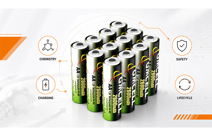
Industrial Battery Reliability Requires More Than High Energy Density
A battery failure in a consumer device may cause temporary inconvenience. In an industrial controller, medical instrument, security system, backup power unit, or remote monitoring device, the same failure can interrupt operations, erase critical data, increase maintenance costs, or compromise system safety.
This is why you cannot engineer a reliable industrial battery around energy density alone. Chemistry selection, charging strategy, thermal behavior, protection architecture, cell consistency, testing, and lifecycle management must all work together around the actual operating requirements of your equipment.
Consumer Electronics Often Prioritize
- Smaller battery dimensions
- Lower weight
- Higher energy density
- Faster charging
Industrial Equipment Requires
- Long-term operating stability
- Predictable service life
- High- and low-temperature tolerance
- Safe and controlled charging
- Practical maintenance and replacement
- Consistent cell and pack performance
- Long-term supply continuity
- Controlled consequences when a failure occurs
Reliability is not a single specification printed on a datasheet. It is a system-level result created throughout the design, manufacturing, validation, and operating life of the battery.
What Makes an Industrial Battery Reliable?
When you evaluate an industrial battery system, reliability cannot be reduced to capacity, voltage, or cycle life alone. A battery may perform well during a laboratory test and still fail prematurely when it is exposed to peak loads, temperature changes, vibration, continuous charging, or long periods of standby operation.
You need to consider how the battery behaves electrically, thermally, mechanically, and operationally throughout its full service life. The following seven dimensions provide a more practical way to judge whether a battery is truly suitable for your equipment.
Stable Electrical Performance
Your battery must keep its voltage within the equipment’s acceptable operating range. It should support both continuous loads and peak-current demands without excessive voltage sag, unexpected shutdowns, or unstable system behavior.
Predictable Service Life
Cycle life only becomes meaningful when it is connected to the actual charge rate, discharge depth, temperature, and duty cycle. You should evaluate cycle life, calendar life, and storage life separately so that replacement intervals can be planned before reliability declines.
Temperature Tolerance
High temperatures can accelerate chemical aging and self-discharge, while low temperatures can reduce usable capacity and power output. Charging limits are often more restrictive than discharge limits, so your design must distinguish between operating temperature and charging temperature.
Safe Charging Behavior
Different chemistries require different charging protocols. An unsuitable charger can cause excessive heating, incomplete charging, accelerated capacity loss, or a serious safety fault. You should treat the charger and battery pack as one integrated power system.
Cell-to-Cell Consistency
A battery pack is often limited by its weakest cell. Differences in capacity, internal resistance, self-discharge, or aging rate can cause uneven charging, premature voltage drop, localized heating, and reduced pack life. Reliable packs depend on careful cell grading and matching.
Mechanical and Environmental Durability
Industrial equipment may be exposed to vibration, impact, dust, humidity, and repeated temperature changes. The pack enclosure, cell supports, insulation, wiring, welds, and connectors must remain secure under the same mechanical and environmental conditions faced by the equipment.
Maintainability and Supply Continuity
A reliable battery should also be practical to inspect, test, replace, and reorder. For equipment with a long service life, you may need the same dimensions, connector, voltage, capacity, and charging behavior to remain available for years. Long-term supply continuity can be just as important as initial battery performance.
A reliable industrial battery must continue to perform safely and predictably under the electrical, thermal, mechanical, and maintenance conditions of your application—not only under ideal laboratory conditions.
Battery Chemistry Must Match the Application
You should not begin battery selection by asking which chemistry is considered the most advanced. Start with the conditions your equipment must handle: voltage range, current demand, available space, charging method, ambient temperature, maintenance access, safety expectations, and required service life.
The correct chemistry is the one that best matches your application’s voltage, load profile, environment, charging method, maintenance model, and safety requirements.
Nickel-Metal Hydride for Stable and Serviceable Systems
Nickel-metal hydride remains relevant when you need a mature rechargeable chemistry with predictable discharge behavior, established charging methods, and practical field replacement. It is frequently considered for industrial controllers, medical instruments, security systems, emergency equipment, embedded electronics, and backup power applications.
Where NiMH Can Fit
- Industrial controllers and PLC backup systems
- Medical and diagnostic equipment
- Security and emergency systems
- Embedded devices and measuring instruments
- Equipment connected to a controlled maintenance charger
Practical Engineering Advantages
- Mature and widely understood chemistry
- Stable voltage and discharge behavior
- Controlled tolerance to limited overcharge
- Simpler protection architecture in many small packs
- Standard and custom pack formats for long-term servicing
Limitations You Need to Consider
- Lower energy density than lithium-ion
- Generally higher self-discharge
- Charging termination requires voltage and temperature monitoring
- Prolonged high-temperature storage can reduce capacity retention
In industrial controllers, medical instruments, security systems, emergency equipment, and embedded backup applications, a properly engineered NiMH Battery can provide a practical balance of stable discharge performance, established charging methods, safety, and long-term serviceability.
Your selection principle: Choose the chemistry that matches the real operating profile of your equipment. A battery with higher energy density may not deliver better reliability when temperature, continuous charging, maintenance, safety, or long-term replacement availability are more important.
Choosing the Right Lithium Chemistry for Industrial Equipment
Lithium-based batteries are not a single technology. Conventional lithium-ion, lithium iron phosphate, and lithium titanate each provide a different balance of energy density, thermal stability, power capability, charging speed, and service life.
Your best option depends on what the equipment must do. A lightweight portable terminal, a frequently cycled storage system, and a high-power machine operating in extreme temperatures may all require different lithium chemistries.
Lithium-Ion for Energy-Dense Industrial Devices
Conventional lithium-ion batteries are often the first option to consider when your equipment must deliver longer operating time without increasing size or weight. Their relatively high cell voltage and energy density make them well suited to portable industrial terminals, wireless inspection equipment, robotics, and mobile measurement systems.
Where It Fits Best
- Portable industrial terminals
- Wireless inspection and sensing devices
- Robotics and mobile automation
- Handheld measurement equipment
- Systems with strict space and weight limits
Why You May Choose It
- High energy density
- Relatively low self-discharge
- Higher voltage per cell
- Suitable for compact product designs
What You Must Control
- Maximum charging voltage
- Overcharge and deep-discharge protection
- High-temperature exposure
- Cell balancing in series-connected packs
Your engineering priority: Lithium-ion performance depends heavily on cell quality, precise charging control, temperature monitoring, protection electronics, and correct pack integration. High energy density alone does not guarantee a safe or reliable system.
Lithium Iron Phosphate for Long-Life Power Systems
Lithium iron phosphate is often selected when your project places greater value on thermal stability, frequent cycling, and predictable long-term operation than on achieving the smallest possible battery. It is widely considered for energy storage systems, industrial vehicles, telecommunications backup, solar energy storage, and lead-acid replacement systems.
Suitable Applications
- Stationary energy storage
- Industrial and utility vehicles
- Telecommunications backup power
- Solar and renewable energy storage
- Lead-acid battery replacement projects
Main Engineering Strengths
- Strong thermal stability
- High cycle-life potential
- Stable operating-voltage platform
- Well suited to frequent cycling
Design Constraints
- More volume may be required than with high-nickel lithium-ion
- Low-temperature charging requires additional control
- The pack still requires a suitable BMS and temperature protection
Do Not Judge Service Life by One Cycle Number
A stated cycle-life figure does not tell you how long an LFP battery will last in your equipment. Actual performance depends on the battery’s depth of discharge, charge and discharge rate, operating temperature, maximum charge voltage, and the point at which the system defines end of life.
Lithium Titanate for Extreme-Duty Applications
Lithium titanate is a specialized option for projects where rapid charging, high power, frequent cycling, or difficult environmental conditions matter more than compact size and low initial cost. You may encounter it in high-duty industrial machinery, fast-charge transport systems, extreme-temperature equipment, and applications that cycle many times each day.
Best-Fit Conditions
High-frequency charging, large power demands, rapid turnaround, temperature extremes, and systems where downtime carries a high operational cost.
Main Strengths
Strong high-rate capability, rapid charging potential, stable cycling behavior, and better low-temperature performance potential than many conventional lithium-ion systems.
Main Trade-Offs
Higher cost and lower energy density can make LTO unnecessary for ordinary industrial equipment where moderate charging speed and conventional operating conditions are acceptable.
When LTO makes sense: Consider it when the cost of downtime, slow charging, cold-weather limitations, or frequent battery replacement is greater than the higher initial battery cost. For standard equipment with moderate demands, another chemistry may provide better overall value.
Lead-Acid for Stationary Backup and Cost-Sensitive Systems
Lead-acid batteries remain practical when your equipment does not require the smallest or lightest possible power source. Their mature supply chain, established charging methods, and relatively low initial cost make them a common choice for uninterruptible power supplies, stationary backup systems, telecommunications equipment, and some industrial vehicles.
They are especially relevant when the battery remains installed in a fixed location, weight is not a critical design constraint, and your system already supports a controlled float-charging architecture.
Where Lead-Acid Still Fits
- UPS and emergency backup systems
- Fixed industrial backup power
- Telecommunications equipment
- Industrial vehicles and material-handling equipment
- Systems where battery weight has limited impact
Why You May Choose It
- Mature and widely understood technology
- Relatively low initial cost
- Broad and established supply chain
- Proven float-charging practices
What You Need to Manage
- High weight and low energy density
- Reduced life under repeated deep discharge
- Faster aging in high-temperature environments
- Need for correct charging voltage and temperature compensation
Your engineering priority: Avoid treating lead-acid as a maintenance-free choice simply because the technology is mature. Correct float voltage, discharge limits, ambient temperature, inspection intervals, and replacement planning all influence whether the battery delivers reliable backup power.
Battery Chemistry Comparison at a Glance
Use this comparison as an initial screening tool rather than a final selection rule. Your battery must still be evaluated against the equipment’s voltage range, current demand, temperature exposure, charging architecture, and maintenance requirements.
| Chemistry | Main Advantage | Main Limitation | Typical Industrial Use |
|---|---|---|---|
| NiMH | Stable, mature, and serviceable | Moderate energy density and generally higher self-discharge | Backup systems, medical equipment, industrial controllers |
| Lithium-ion | High energy density | Requires strict voltage, temperature, and safety control | Portable industrial devices, robotics, wireless equipment |
| LiFePO4 | Thermal stability and long-cycle potential | Lower energy density than some lithium-ion systems | Energy storage, industrial vehicles, backup power |
| LTO | High-rate and long-cycle capability | High cost and relatively low energy density | Extreme-duty equipment and fast-charge systems |
| Lead-acid | Proven and economical | Heavy and sensitive to repeated deep discharge | UPS systems, telecom, stationary backup power |
Chemistry selection should begin with your application requirements rather than market popularity. A chemistry that performs well in a portable device may not be the best option for a continuously charged backup system or a high-temperature industrial installation.
Why Energy Density Is Only One Selection Factor
Higher energy density can help you reduce battery size and weight, but it does not automatically make a battery safer, longer-lasting, or better suited to industrial use. Before you prioritize watt-hours per kilogram, consider how the battery will behave during startup loads, standby periods, temperature changes, charging, maintenance, and eventual replacement.
The questions below help you evaluate the complete industrial battery operating profile rather than choosing a chemistry from one headline specification.
| Selection Factor | Engineering Question |
|---|---|
| Energy density | How much runtime do you need within the available battery space and weight limit? |
| Voltage profile | Can your equipment operate reliably across the battery’s full discharge-voltage range? |
| Peak current | Can the battery support motor startup, wireless transmission, valve activation, or other short pulse loads? |
| Cycle life | How frequently will the battery be charged, discharged, and returned to service? |
| Calendar life | How long must the battery remain installed, including time spent idle or on standby? |
| Self-discharge | Will the battery spend long periods in storage, standby, or disconnected from a charger? |
| Charging complexity | Can your device support the required charger, sensors, protection circuit, and cell-balancing functions? |
| Temperature | Will the battery operate, charge, or remain in storage under high or low temperatures? |
| Maintenance | Can technicians inspect, test, access, and replace the battery without excessive downtime? |
| Safety | What happens to the equipment, operator, and surrounding system if one cell fails? |
| Lifecycle cost | What is the total cost of the battery, charger, maintenance, replacement labor, downtime, and disposal? |
Which battery stores the most energy?
Which battery will continue to operate safely, predictably, and economically under the real conditions of my equipment?
For many industrial power systems, predictable voltage behavior, safe continuous charging, practical serviceability, and long-term replacement availability may be more valuable than achieving the maximum possible watt-hours per kilogram.
Charging Protocols Must Follow Battery Chemistry
There is no universal charging method for industrial batteries. A charging protocol that is suitable for one chemistry may reduce the life, capacity, or safety of another. Before you select a charger, you need to understand how the battery responds to current, voltage, temperature, and time as it approaches full charge.
In a reliable industrial battery system, the charger is not a separate accessory. It is part of the battery design. Its control logic must match the chemistry, cell configuration, expected temperature range, duty cycle, and required service life of your equipment.
The correct charger must recognize when the battery is approaching full charge, respond to temperature changes, limit electrical stress, and stop or reduce charging before the cells are damaged.
Charging NiMH Battery Systems
A NiMH battery pack is commonly charged with controlled current rather than a fixed-voltage method. As the cells approach full charge, their voltage response becomes less distinct and more of the incoming energy begins to appear as heat. For this reason, you should not rely on one fixed voltage threshold to determine when charging is complete.
A reliable NiMH charger normally combines more than one termination method. Voltage response, temperature rise, elapsed time, and maximum pack temperature can work together to prevent excessive overcharge.
Constant-Current Charging
The charger supplies a controlled current selected according to cell capacity, charging time, temperature limits, and the pack’s ability to release heat.
Negative Delta V Detection
The charger detects the small voltage drop that may appear after the cells reach full charge and uses it as one signal to stop fast charging.
Temperature Monitoring
A thermistor allows the charger to monitor pack temperature and stop charging if the battery approaches an unsafe or damaging limit.
Temperature-Rise Detection
The rate of temperature increase can help identify when charge acceptance is falling and more energy is being converted into heat.
Timer Backup
A maximum charging-time limit provides an additional safeguard if the main voltage or temperature termination signal is not detected.
Maintenance Charging
A carefully controlled low current may be used to compensate for self-discharge, but excessive continuous current can increase temperature and shorten battery life.
At Low Charge Rates
The negative Delta V signal may be small or difficult to detect. Timer limits and temperature monitoring become more important.
At High Charge Rates
Faster charging can increase heat generation, making accurate temperature sensing and timely termination essential.
During Continuous Charging
Maintenance current must be low enough to avoid persistent heat and long-term overcharge stress.
Thermistor placement matters: In a multi-cell NiMH battery pack, the sensor should be positioned where it can detect the cells most likely to accumulate heat. A poorly placed sensor may report a lower temperature than the hottest area inside the pack.
Charging Lithium-Ion Battery Systems
Lithium-ion charging requires precise control because the cells have limited tolerance for excessive voltage. Most systems use a constant-current, constant-voltage charging process, commonly called CC-CV.
Constant Current
The charger supplies a controlled current while cell voltage rises.
Voltage Limit Reached
The cell reaches its permitted maximum charging voltage.
Constant Voltage
Voltage remains controlled while the charging current gradually decreases.
Current Tapers
The current falls as the battery approaches full charge.
Charging Stops
Charging ends when current falls to the defined termination level.
Avoid Continuous Overvoltage
Lithium-ion cells should not remain above their permitted charging voltage. Even a small persistent overvoltage can accelerate degradation and increase risk.
Balance Series-Connected Cells
In multi-cell packs, one cell may reach its upper voltage limit before the others. Balancing helps prevent individual cells from becoming overcharged.
Control Low-Temperature Charging
Charging at low temperature can increase the risk of lithium plating. Current limits or charging lockout may be necessary.
Match Charger and Protection System
A protection circuit or BMS can interrupt abnormal conditions, but it cannot convert an unsuitable charger into a correctly controlled charging system.
Lithium-ion reliability depends on precise control of cell voltage, current, temperature, and pack balance.
Charging Lead-Acid Battery Systems
Lead-acid charging normally uses several stages so that the battery can recover capacity without remaining at an excessive voltage. The exact voltage limits depend on battery construction, temperature, application, and whether the system is cycled regularly or kept on standby.
Bulk Charging
The charger supplies a relatively high controlled current until the battery reaches the absorption-voltage level.
Absorption Charging
Voltage is held within a controlled range while current gradually decreases as the battery approaches full charge.
Float Charging
The charger lowers the voltage to maintain readiness without continuously applying the higher absorption voltage.
Temperature Compensation
Charging voltage is adjusted according to battery temperature to reduce overcharge at high temperature and undercharge at low temperature.
If Float Voltage Is Too High
The battery may experience increased gassing, water loss, grid corrosion, heat, and accelerated aging.
If Float Voltage Is Too Low
The battery may remain partially charged, reducing available backup capacity and increasing the risk of sulfation.
High-temperature operation: In many lead-acid backup systems, charging voltage should be reduced as battery temperature rises. Using one fixed voltage across all temperatures can shorten service life.
Advanced and Adaptive Charging Strategies
More advanced chargers can adjust their behavior according to temperature, state of charge, battery age, or recent usage. These methods may improve charging efficiency or reduce stress in specific applications, but they are not automatically better for every battery.
Any adaptive strategy must be validated using the actual cells, pack configuration, operating temperature, and load profile found in your equipment.
Pulse Charging
Current is delivered in pulses separated by rest periods. Results depend on pulse amplitude, duration, chemistry, temperature, and cell design.
Adaptive Current Control
Charging current changes according to cell voltage, temperature, impedance, or estimated state of charge.
Temperature-Based Adjustment
The charger reduces current, modifies voltage, or pauses charging when cell temperature moves outside the preferred range.
SOC-Dependent Limits
Charging current or voltage limits change as the battery approaches full charge to reduce electrical and thermal stress.
Usage-Pattern Charging
The system adjusts charging according to expected operating schedules, standby periods, required reserve capacity, or maintenance windows.
Pulse-based and adaptive charging methods may improve temperature control or charging efficiency in specific systems, but their benefits depend on chemistry, cell design, current profile, and control accuracy. They must be validated with the actual battery rather than assumed to be universally beneficial.
Depth of Discharge and Operating Windows
Depth of discharge describes how much of the battery’s available capacity you use before recharging it. A 100% depth of discharge means the battery has delivered essentially all of its usable capacity within the defined voltage limits. It does not describe a gentle or partial discharge.
Shallower cycling often reduces stress and can improve cycle life, but designing every system around very shallow discharge is not always practical. You may need a larger, heavier, and more expensive battery to provide the same usable runtime while keeping each cycle shallow.
The right operating window must balance usable capacity, required runtime, reserve energy, equipment weight, replacement cost, and the expected number of charge-discharge cycles.
Shallow Discharge
Only a limited portion of the available capacity is used. This may reduce cycling stress, but it requires enough installed capacity to support the required runtime.
Balanced Operating Window
A controlled mid-range operating window may provide a practical balance between usable energy, battery size, cycle life, and cost.
Deep Discharge
Most usable capacity is removed before recharging. This maximizes runtime from the installed battery but may increase stress depending on chemistry and operating conditions.
Different Chemistries Respond Differently to Deep Discharge
NiMH
A series-connected NiMH pack must be protected from excessive discharge because weaker cells may reach empty first and face reverse-polarity stress if the load continues.
Lithium-Ion
Low-voltage cut-off is essential. Allowing individual cells to remain below their permitted range can cause irreversible degradation and create charging risks.
Lead-Acid
Repeated deep discharge can shorten life significantly, particularly when the battery remains partially discharged or is not promptly recharged.
LiFePO4
This chemistry may support frequent controlled cycling, but actual life still depends on temperature, charge voltage, current, depth of discharge, and pack balance.
Your Operating Window Should Reflect the Application
UPS and Backup Power
Your system may need to preserve enough reserve capacity to support a controlled shutdown, emergency operation, or a specified backup duration after the main power fails.
Industrial Robotics
You must balance runtime per shift, charging opportunities, battery weight, equipment utilization, and the number of cycles expected during the service period.
NiMH Backup Packs
A backup NiMH pack may remain connected to controlled maintenance charging for long periods and experience only occasional discharge during power interruptions.
Energy Storage Systems
Storage systems may perform one or more managed cycles each day while reserving capacity for grid support, peak demand, or unexpected outages.
Avoiding unnecessary deep discharge can reduce battery stress, but the optimum operating window depends on chemistry, required runtime, reserve capacity, weight, cost, and replacement strategy.
NiMH and Lithium-Ion Require Different Engineering Priorities
NiMH and lithium-ion batteries can both support industrial equipment, but they do not require the same charging, protection, thermal, or maintenance approach. Your choice should begin with the way the device operates rather than with a general assumption that one chemistry is always more advanced.
A portable high-energy device may benefit from lithium-ion, while a serviceable backup system or continuously maintained industrial device may place greater value on the established behavior and simpler pack architecture of NiMH.
| Engineering Factor | NiMH | Lithium-Ion |
|---|---|---|
| Nominal cell voltage | About 1.2V | About 3.6–3.7V for many common chemistries |
| Energy density | Moderate | High |
| Charging method | Constant current with voltage, temperature, and time-based termination | CC-CV with strict maximum-voltage control |
| Overcharge tolerance | Relatively tolerant under controlled conditions | Low tolerance; overvoltage must be prevented |
| Protection architecture | Often focused on charger termination, temperature sensing, timers, fuses, and thermal protection | Focused on voltage, current, temperature, short-circuit protection, and cell balancing |
| Self-discharge | Generally higher | Generally lower |
| Maintenance charging | Possible when current and temperature are properly controlled | Continuous trickle charging is generally unsuitable |
| Pack complexity | Often simpler in smaller industrial systems | Usually higher in multi-cell systems |
| Typical industrial role | Backup systems, medical devices, embedded equipment, and serviceable systems | Portable equipment, lightweight devices, robotics, and high-energy systems |
Engineers comparing the two technologies should evaluate charging architecture, protection requirements, operating temperature, maintenance access, expected service life, size, and weight—not energy density alone. A more detailed nimh battery vs lithium ion comparison can help clarify which chemistry better matches a specific industrial application.
Neither chemistry is universally superior. Your objective is to select the technology whose strengths align with the actual duty cycle, maintenance model, environmental exposure, and risk profile of the equipment.
Thermal Management at Cell, Pack, and System Level
Thermal management does not always mean liquid cooling or a complex HVAC system. The controls you need depend on battery chemistry, pack size, current level, charging rate, enclosure design, ambient conditions, and the consequences of a temperature-related failure.
In a small industrial backup battery pack, correct charging current and thermistor placement may matter more than active cooling. In a large lithium battery installation, you may need continuous temperature monitoring, controlled airflow, liquid cooling, and measures to limit thermal propagation.
Small Industrial Battery Packs
Small packs often rely on passive design choices and accurate charging control rather than active cooling hardware.
- Charge current matched to cell capacity and pack cooling
- Adequate spacing between cells
- Enclosure ventilation and heat-release paths
- Thermistor and thermal-switch protection
- Wire gauge selected for expected current
- PCB layout that avoids concentrated heating
- Reliable charge-termination logic
Large Lithium Battery Systems
Large lithium systems may generate and retain significantly more heat, making active temperature management and fault containment necessary.
- Forced-air cooling
- Liquid cooling circuits
- HVAC-controlled enclosures
- Multi-point temperature monitoring
- Thermal-propagation barriers
- Cooling plates and thermal interface materials
- BMS-controlled current or shutdown responses
Thermal Considerations for NiMH Battery Packs
Temperature is especially important during the final stage of NiMH battery charging. As charge acceptance decreases, more of the supplied energy can be converted into heat. A rapid temperature rise may therefore indicate that the cells are approaching or have reached full charge.
End-of-Charge Heating
Temperature rise near full charge should be detected and used together with voltage and timer controls to prevent excessive overcharge.
High-Temperature Aging
Elevated temperature can increase self-discharge and accelerate capacity loss during storage, standby operation, and repeated charging.
Maintenance-Charge Stress
Continuous maintenance current that is too high can keep the pack warm and shorten life even when the equipment is operating normally.
Thermistor Placement
Position the sensor near the cells or internal area most likely to accumulate heat rather than simply placing it where installation is easiest.
Avoid Localized Hotspots
Cell spacing, insulation, wiring, enclosure shape, nearby heat-producing electronics, and airflow should be reviewed together. The average pack temperature may appear acceptable while one cell or one internal region operates substantially hotter than the rest.
Questions to Ask About Thermal Design
Where is heat generated during charging and peak discharge?
Can heat escape from the enclosure during continuous operation?
Does the temperature sensor represent the hottest cells?
Will nearby electronics increase battery temperature?
Does the charger reduce current or stop at unsafe temperatures?
Has the pack been tested at maximum ambient temperature?
Thermal management does not always require complex cooling hardware. In many smaller battery packs, correct charge rate, temperature sensing, component placement, ventilation, and enclosure design provide the most important controls.
Safety by Design: From Cell Selection to Fault Protection
Battery safety should not depend on one electronic component. A BMS, fuse, thermistor, or protection circuit can reduce specific risks, but none of these devices can compensate for unsuitable cells, poor pack construction, an incorrect charger, or operation outside the battery’s intended limits.
A reliable industrial battery safety system uses several layers. Each layer should help prevent faults, detect abnormal conditions, limit damage, and confirm through testing that the complete battery system behaves as expected.
Cell-Level Safety
Begin with the correct chemistry, stable cells, controlled current, and consistent production quality.
Pack-Level Safety
Use protective components, reliable connections, insulation, and mechanical support inside the pack.
System-Level Safety
Monitor voltage, current, and temperature, then respond before abnormal conditions become dangerous.
Validation-Level Safety
Test normal use, foreseeable misuse, environmental exposure, and long-term operating stress.
Cell-Level Safety
Safety begins before pack assembly. You need cells whose chemistry, current capability, temperature range, capacity, and physical format match the real duty cycle of the equipment. A protection circuit cannot make an unsuitable cell suitable for the application.
Match Chemistry to the Risk Profile
Choose the chemistry according to voltage, load, charging method, temperature, service access, and the consequences of battery failure.
Use Consistent, Qualified Cells
Stable cell quality helps reduce unexpected differences in capacity, internal resistance, self-discharge, and thermal behavior.
Control Charge and Discharge Rates
Current limits should reflect the cell specification, pack temperature, expected runtime, connector capability, and available cooling.
Maintain Batch Consistency
Cells from controlled production lots are easier to match and trace than cells collected from unrelated batches or uncertain sources.
Do Not Mix New, Aged, Damaged, or Unqualified Cells
Mixing cells with different capacities, resistance levels, usage histories, or self-discharge rates can create uneven charging and discharge behavior. In a series-connected battery pack, the weakest cell may become the first point of failure.
Pack-Level Safety
Once individual cells are connected, the pack needs components and construction methods that limit current, detect heat, prevent short circuits, resist vibration, and keep wiring and connectors secure throughout the equipment’s service life.
Fuse
Interrupts excessive current before wires, cells, or connected equipment are damaged.
Thermistor
Provides real-time temperature information to the charger or system controller.
Thermal Switch
Opens the circuit when temperature exceeds a defined safety limit.
Insulation Barriers
Separate conductive surfaces and help prevent abrasion, short circuits, and accidental contact.
Cell Spacing
Supports heat release, reduces friction, and helps prevent concentrated pressure between cells.
Correct Wire Gauge
Limits resistive heating and voltage drop under continuous and peak current.
Reliable Welding
Stable welding helps reduce intermittent connections, local resistance, and heat generation.
Mechanical Reinforcement
Keeps cells, wiring, and protective components secure during vibration, impact, and transport.
Strain Relief
Prevents cable movement from transferring mechanical force to solder joints, welds, or connectors.
Connector Polarity Control
Keyed connectors, clear markings, and production checks help prevent reverse connection.
Pack-level principle: Protective components must be selected according to the battery’s maximum current, charging behavior, fault energy, temperature range, and mechanical environment. A component added without correct sizing may create a false sense of safety.
System-Level Safety
System-level safety connects the battery, charger, load, sensors, protection electronics, and equipment software. The objective is not only to detect a fault, but also to reduce current, stop charging, disconnect the load, alert the operator, or place the equipment into a controlled state.
Charger Termination
Stops or reduces charging according to the chemistry’s voltage, current, temperature, and time requirements.
Overvoltage Protection
Prevents individual cells or the complete pack from exceeding permitted charging limits.
Undervoltage Protection
Disconnects the load before cells enter a damaging or unsafe over-discharge condition.
Overcurrent Protection
Responds to excessive load current, stalled motors, wiring faults, or short-circuit conditions.
Temperature Monitoring
Uses one or more sensors to control charging, reduce output, or stop operation when temperature moves outside the approved range.
Fault Shutdown
Places the battery or equipment into a defined safe state when critical limits are exceeded.
Load Management
Reduces nonessential loads, limits startup current, or protects reserve capacity during abnormal conditions.
Warning and Diagnostic Functions
Record faults and alert technicians before battery degradation or abnormal operation causes unexpected downtime.
Validation-Level Safety
Safety assumptions should be verified with the actual cell, pack, charger, enclosure, wiring, and equipment. Testing should reproduce normal operation, foreseeable misuse, environmental exposure, and the battery’s expected aging condition.
Overcharge Testing
Evaluates charger termination and pack response when charging continues abnormally.
Short-Circuit Testing
Checks current interruption, wire heating, cell response, and protective-device operation.
Temperature Testing
Confirms safe charging, discharge, storage, and protection behavior across the intended range.
Vibration Testing
Evaluates welds, wiring, connectors, supports, insulation, and mechanical retention.
Mechanical Shock and Drop
Checks whether impact can loosen cells, damage insulation, or interrupt electrical connections.
Abnormal Charging
Examines incorrect current, failed sensors, charger faults, or charging outside approved temperatures.
Reverse-Polarity Evaluation
Confirms that connectors, markings, and protection measures limit damage from incorrect connection.
Long-Term Cycle Testing
Identifies how aging affects capacity, internal resistance, temperature, balance, and protection thresholds.
A safety component should not be treated as permission to operate the battery outside its intended limits. Reliable systems combine prevention, detection, protection, and validation.
Does Every Industrial Battery Need a BMS?
Not every battery pack requires the same type of battery management system. The required electronics depend on chemistry, cell count, pack voltage, fault energy, charging method, temperature exposure, equipment risk, and the level of information the system must provide.
A multi-cell lithium-ion battery system usually needs continuous voltage, current, temperature, and balance management. A small NiMH battery pack may use a simpler architecture focused on charging termination, temperature detection, timer limits, and passive protective components.
Lithium-Ion Systems
Multi-cell lithium-ion packs usually require an electronic BMS because individual cells have strict upper and lower voltage limits and may drift apart during use.
- Cell voltage monitoring
- Pack current monitoring
- Temperature sensing
- Cell balancing
- Overcharge and over-discharge protection
- Short-circuit and overcurrent protection
- State-of-charge estimation
- State-of-health estimation
NiMH Systems
Small NiMH packs may not need continuous individual-cell monitoring or active balancing, but they still need protection suited to their charging behavior, temperature response, current level, and application.
- Chemistry-appropriate charging control
- Temperature detection
- Maximum charging-time protection
- Pack fuse
- Thermal switch when required
- Pack-voltage monitoring where the application requires it
For a continuously charged NiMH backup battery, charger termination, maintenance-current control, and temperature sensing may be more important than a lithium-style balancing circuit.
Questions That Determine the Required Protection Architecture
Which battery chemistry is being used?
How many cells are connected in series?
What are the continuous and peak current demands?
What charging method and termination logic are used?
Must the system estimate remaining runtime or battery health?
What happens if the battery fails or disconnects?
Will the battery operate in extreme temperatures?
Is remote fault reporting or predictive maintenance required?
Small NiMH packs do not always require the same BMS architecture used in multi-cell lithium-ion systems. However, simpler electronics do not mean that charging control, temperature monitoring, and protective components can be ignored.
Cell Matching and Pack Consistency
When several cells are connected into a battery pack, they no longer operate as completely independent components. The same current flows through cells connected in series, but differences in capacity, resistance, temperature, and aging can cause each cell to reach its operating limits at a different time.
This is why an industrial battery pack is often limited by its weakest cell. A pack may contain many acceptable cells, yet one poorly matched cell can reduce usable capacity, increase heat, trigger early shutdown, or shorten the life of the entire assembly.
A battery pack is limited by its weakest cell.
Cell Matching Requires More Than Similar Voltage
Two cells can show a similar open-circuit voltage and still behave differently under load or during charging. Reliable matching should consider the characteristics that influence how cells share electrical and thermal stress throughout the pack lifecycle.
Capacity
Cells should deliver similar usable capacity so that one cell does not reach empty substantially earlier than the others.
Internal Resistance
Higher-resistance cells can experience greater voltage drop and heat generation during peak-current operation.
Open-Circuit Voltage
Voltage screening can help identify obvious differences before assembly, but it should not be used as the only matching criterion.
Self-Discharge
Cells that lose charge at different rates can develop unequal states of charge during long storage or standby periods.
Charge Acceptance
Cells should respond similarly to the selected charging current and termination method so that one cell does not overheat or reach full charge too early.
Discharge Curve
Similar discharge behavior helps the pack maintain a predictable voltage profile under both continuous and pulse loads.
Production Batch
Cells from controlled production batches are more likely to share similar materials, processes, and performance characteristics.
Aging Condition
New and aged cells should not be mixed casually. Usage history can change capacity, resistance, self-discharge, and temperature behavior.
What Happens When Cells Are Poorly Matched?
Poor matching creates differences that usually become more visible as the battery ages. A small variation at the beginning of pack life may develop into a substantial imbalance after repeated charging, deep discharge, storage, or exposure to uneven temperature.
One Cell Empties First
A lower-capacity cell can reach its discharge limit while the rest of the pack still appears to contain usable energy.
One Cell Reaches Full Charge First
The earliest full cell may experience additional overcharge stress while the remaining cells continue charging.
Localized Overcharge
Uneven charge acceptance can cause one part of the pack to generate more heat or experience greater chemical stress.
Reverse-Polarity Risk
In some series-connected packs, continued discharge after a weak cell is empty may force that cell into reverse polarity.
Abnormal Heating
High-resistance cells, poor welds, or uneven charging can create hotspots that are not visible from average pack temperature.
Reduced Pack Capacity
The usable capacity of the complete pack may be determined by the cell that first reaches its charge or discharge limit.
Shorter Cycle Life
Repeated imbalance can accelerate degradation in the weakest cells, reducing pack runtime and increasing the frequency of battery replacement.
Why Matching Matters in Series-Connected NiMH Packs
In a series-connected NiMH battery pack, all cells carry the same current, but they may not reach empty or full charge at the same time. Matching becomes especially important when the pack is expected to provide long backup duration, frequent cycling, or many years of service.
Lower-Capacity Cells Empty Earlier
Near the end of discharge, a lower-capacity cell may reach empty before the rest of the pack.
Continued Discharge Can Create Reversal
If the load continues after a weak cell is depleted, the other cells may force current through it in reverse.
High-Resistance Cells Run Hotter
A cell with higher internal resistance may generate additional heat during both charging and high-current discharge.
Self-Discharge Creates SOC Differences
After long storage, cells with higher self-discharge may begin operation at a lower state of charge than the rest of the pack.
Industrial pack assembly is not simply the process of connecting individual cells. Cell grading, matching, welding, thermal design, insulation, and final testing determine whether the cells will operate as a consistent system.
Testing and Validation Under Real Operating Conditions
Standard cell tests provide valuable baseline data, but they do not automatically prove that a battery will perform reliably inside your equipment. The completed pack must also be evaluated with the actual charger, wiring, enclosure, load profile, operating temperature, storage pattern, and maintenance process.
A strong validation plan combines electrical testing, environmental testing, mechanical testing, and application-level testing. Each test should answer a practical question about how the battery will behave in the field.
Electrical Testing
Confirm that the pack can deliver the required capacity, voltage, current, and charge retention throughout its expected operating range.
- Initial capacity measurement
- Rated capacity verification
- Internal-resistance measurement
- Cell and pack voltage consistency
- Peak-current capability
- Charge retention and self-discharge
- Overcharge response
- Deep-discharge response
Environmental Testing
Verify that temperature, humidity, storage, and repeated environmental changes do not create unacceptable performance loss or safety risks.
- High-temperature operation
- Low-temperature operation
- Temperature cycling
- Humidity exposure
- Storage aging
- Thermal shock
Mechanical Testing
Confirm that cells, welds, wires, insulation, connectors, and enclosure features remain secure during handling and operation.
- Vibration
- Mechanical shock
- Drop testing
- Compression
- Connector retention
- Wire-pull strength
- Welding-strength verification
Application-Level Testing
A battery that passes cell-level testing may still behave differently after it is installed inside the final product. Enclosure temperature, connector resistance, startup current, charger tolerances, software limits, and nearby electronics can all change real-world performance.
Charge and Discharge in the Actual Device
Reproduce the real operating cycle using the final charger, load, wiring, and enclosure.
Measure Startup and Peak Current
Confirm that motors, radios, valves, displays, or processors do not create excessive voltage sag.
Verify Low-Voltage Shutdown
Check that the equipment disconnects or shuts down before the battery enters a damaging discharge condition.
Confirm Charger Compatibility
Validate charge current, voltage, termination logic, sensor response, and behavior after power interruptions.
Check Internal Enclosure Temperature
Measure the battery and surrounding electronics under maximum ambient temperature and full operating load.
Simulate Power Failure and Backup Operation
Confirm backup runtime, transfer behavior, alarm functions, data retention, and controlled shutdown.
Verify Abnormal-System Responses
Test how the system responds to charger failure, disconnected sensors, excessive load, reversed connectors, high temperature, low voltage, and other foreseeable faults.
Validation Priorities Change with the Application
Medical Equipment
- Stable power delivery
- Fault-safe operation
- Predictable replacement intervals
- Temperature control
Remote Sensors
- Self-discharge
- Long-term storage
- Maintenance interval
- Extreme-temperature performance
Industrial Controllers
- Backup runtime
- Data and configuration retention
- Maintenance or trickle charging
- Voltage behavior after aging
Mobile Equipment
- Battery weight
- Peak power
- Charging time
- Cycle life
The correct validation profile should reproduce the battery’s actual duty cycle, charging pattern, environmental exposure, storage time, and maintenance conditions.
Engineering for Lifecycle Performance
Battery lifecycle performance is determined long before the first production pack enters service. Decisions made during product definition influence the battery’s charging stress, operating temperature, maintenance requirements, replacement frequency, and long-term reliability.
To achieve predictable performance, you need to manage the battery through four connected stages: development, qualification, production, and field operation. Information collected at each stage should improve the decisions made in the next.
Development
Define the electrical, mechanical, thermal, charging, safety, and maintenance requirements.
Qualification
Verify that the proposed battery performs safely inside the actual equipment and environment.
Production
Convert the approved design into a repeatable product through controlled processes and testing.
Field Operation
Monitor aging, maintain the battery, plan replacement, and return field data to future designs.
Development Stage
During development, your first task is to define what the equipment actually requires. Selecting a battery from nominal voltage and capacity alone can lead to poor runtime, excessive weight, incorrect charging, premature aging, or an unsuitable protection architecture.
Nominal Voltage
Determine the voltage the equipment is designed around and how many cells are required in series.
Operating-Voltage Range
Confirm the highest and lowest battery voltage at which the equipment can operate safely and reliably.
Continuous Current
Calculate the current the battery must provide during normal operation without excessive heat or voltage drop.
Peak Current
Identify startup, motor, radio-transmission, valve, processor, and other short-duration pulse loads.
Required Runtime
Define how long the device must operate between charges or after the primary power supply fails.
Available Space
Review the battery compartment, cell arrangement, wiring, connector, insulation, ventilation, and service access.
Weight Limit
Decide whether battery weight affects portability, vehicle efficiency, operator comfort, or mounting strength.
Temperature Range
Separate storage, charging, and discharge temperatures because the permitted limits may be different.
Charging Method
Select charging logic that matches the chemistry, charge rate, temperature range, and standby requirements.
Maintenance Access
Determine whether technicians can inspect, test, disconnect, and replace the battery without major disassembly.
Safety Requirements
Define the required electrical, thermal, mechanical, charging, and fault-response safeguards.
Certification Requirements
Identify applicable product, transport, environmental, market-access, and customer-specific requirements early in development.
Qualification Stage
Qualification is where you confirm that the proposed battery design works under the electrical, thermal, mechanical, and operational conditions expected in the field. Testing should use representative cells, pack components, chargers, connectors, enclosures, and equipment settings.
Prototype Testing
Confirm voltage, capacity, runtime, current capability, dimensions, connector fit, and mechanical installation.
Charger Compatibility
Verify charging current, voltage limits, termination behavior, sensor operation, and recovery after power interruption.
Cycle-Life Testing
Reproduce the expected charge rate, discharge depth, rest periods, temperature, and end-of-life criteria.
Environmental Testing
Evaluate high temperature, low temperature, humidity, storage aging, thermal cycling, and shock exposure.
Device-Level Validation
Test the battery inside the final equipment under real loads, enclosure temperatures, charging conditions, and shutdown limits.
Failure Analysis
Investigate abnormal heat, voltage sag, early capacity loss, poor charging, connector faults, and cell imbalance.
Safety Verification
Confirm that charging termination, fuses, thermal protection, voltage limits, fault shutdown, insulation, and mechanical controls behave as intended under both normal and abnormal conditions.
Production Stage
A qualified prototype only proves that one design can work. Production engineering must ensure that every approved batch delivers comparable electrical, mechanical, thermal, and safety performance.
Incoming Cell Inspection
Confirm model, appearance, voltage, capacity, resistance, production lot, and supplier documentation.
Cell Grading
Separate cells according to measured performance before they are assigned to battery packs.
Cell Matching
Combine cells with compatible capacity, resistance, voltage, self-discharge, and aging characteristics.
Welding Control
Control weld position, strength, resistance, material, and process parameters to reduce connection faults.
Connector Inspection
Verify connector type, polarity, pin assignment, retention, wire length, strain relief, and contact quality.
Insulation Inspection
Check barriers, sleeves, pads, wire routing, exposed conductors, abrasion points, and enclosure clearances.
Final Charge and Discharge Testing
Confirm pack voltage, capacity, charging behavior, discharge response, temperature, and protection functions.
Traceability
Link finished packs to cell lots, test records, operators, components, production dates, and process conditions.
Batch Control
Compare production batches against approved limits so that changes in cell performance, materials, welding, wiring, or assembly do not reach customers unnoticed.
Field Operation Stage
Once the battery enters service, it will gradually lose capacity and increase in resistance. Your maintenance strategy should identify whether this aging remains within the expected range or whether abnormal operating conditions are accelerating degradation.
Periodic Capacity Checks
Verify whether the battery still provides the runtime or backup duration required by the equipment.
Monitor Charging-Time Changes
Unexpectedly short or long charging time may indicate capacity loss, charger faults, sensor problems, or increased resistance.
Watch for Abnormal Heating
Compare battery temperature under similar loads and charging conditions to identify developing faults.
Track Internal Resistance
Increasing resistance can reduce peak-current performance, increase voltage sag, and create additional heat.
Record Fault Events
Document low-voltage events, charger alarms, excessive temperature, shutdowns, connection faults, and premature replacements.
Plan Preventive Replacement
Replace batteries before capacity or power capability falls below the minimum required by the application.
Feed Field Data Back into the Next Design
Use real service data to improve capacity sizing, chemistry selection, charging limits, thermal design, protection settings, maintenance intervals, and production tests in the next product generation.
Lifecycle performance begins during product definition. It cannot be added after the battery has already entered production.
From Preventive to Predictive Battery Maintenance
Preventive maintenance replaces or tests batteries according to a fixed schedule. Predictive maintenance adds another layer by using operating data to identify whether an individual battery is aging normally or showing signs of an abnormal condition.
This does not mean every industrial device needs cloud connectivity, complex artificial intelligence, or a digital twin. The appropriate level of monitoring should reflect the value of the equipment, the cost of downtime, the size of the battery system, and the amount of useful data the system can collect reliably.
Preventive Maintenance
Batteries are inspected, tested, or replaced according to expected service life, calendar intervals, cycle count, or equipment maintenance schedules.
- Simple to implement
- Suitable for smaller device populations
- May replace healthy batteries early or miss abnormal degradation between inspections
Predictive Maintenance
Historical and real-time data are used to detect abnormal trends and estimate when inspection or replacement may be required.
- Helps identify abnormal aging earlier
- Supports maintenance planning across large fleets
- Requires reliable sensors, data quality, trend interpretation, and validated thresholds
What Battery Data Can You Collect?
The most useful data depend on the battery chemistry and system architecture. You do not need to collect every possible measurement. Focus on parameters that can reveal changes in capacity, resistance, charging behavior, temperature, balance, and equipment load.
Pack Voltage
Reveals overall charging, discharge, and low-voltage behavior.
Cell Voltage
Helps identify imbalance in systems that support individual-cell monitoring.
Charge Current
Shows whether the charger is following the expected charging profile.
Discharge Current
Identifies changing equipment loads, pulse events, and unexpected current demand.
Temperature History
Reveals repeated overheating, poor ventilation, high ambient exposure, or charging stress.
Charge Duration
A changing charge time may indicate reduced capacity, higher resistance, or charger problems.
Internal Resistance
Increasing resistance can reduce power capability and increase heating.
Capacity Trend
Tracks whether runtime is declining at the expected rate.
Cell Imbalance
Shows whether differences between cells are increasing with age.
Fault Events
Records temperature, voltage, current, charging, communication, and shutdown alarms.
Storage Duration
Helps explain self-discharge, calendar aging, and long periods without maintenance charging.
Number of Cycles
Provides context when combined with discharge depth, temperature, current, and elapsed calendar time.
What Problems Can Condition Data Reveal?
| Observed Trend | Possible Meaning | Recommended Response |
|---|---|---|
| Abnormal capacity decline | Accelerated aging, excessive temperature, overcharge, deep discharge, cell imbalance, or unsuitable duty cycle | Inspect charging, temperature, usage history, and cell consistency |
| Internal resistance continues rising | Cell aging, connection deterioration, corrosion, welding problems, or thermal stress | Check voltage sag, heat, connectors, welds, and replacement threshold |
| Charging time changes | Capacity loss, incorrect termination, reduced charge acceptance, charger drift, or sensor error | Compare charging current, voltage, temperature, and termination records |
| Cell imbalance increases | Uneven aging, self-discharge differences, thermal variation, poor matching, or balancing limitations | Evaluate affected cells, pack balance, thermal distribution, and replacement need |
| Local temperature rises | High-resistance cell, poor connection, excessive current, restricted ventilation, or charger problem | Inspect the hotspot, wiring, cell resistance, charging, and enclosure airflow |
| Equipment load increases | Motor wear, software changes, additional accessories, mechanical resistance, or component degradation | Confirm whether the battery still meets current and runtime requirements |
| Charger performance changes | Component aging, calibration drift, unstable input power, failed temperature sensing, or incorrect firmware behavior | Test the charger separately and confirm voltage, current, temperature, and termination limits |
Match the Monitoring Strategy to the System
Small Industrial Devices
A small controller, medical instrument, alarm system, or backup device may not justify continuous remote monitoring.
- Periodic capacity testing
- Visual inspection
- Charging-time records
- Replacement-date records
- Temperature and fault checks during scheduled maintenance
Large Storage and Vehicle Systems
Large battery systems have higher fault energy, more cells, greater replacement cost, and more operational data available.
- Continuous voltage and temperature logging
- Cell-balancing trends
- Charge and discharge history
- State-of-health modeling
- Fleet-level maintenance and replacement planning
Predictive maintenance does not eliminate battery aging. Its value lies in identifying abnormal degradation early enough to schedule inspection or replacement before the battery causes equipment downtime.
Failure Analysis and Risk Assessment
When an industrial battery delivers low runtime, overheats, loses balance, or shuts equipment down unexpectedly, replacing the pack may restore operation temporarily. It does not necessarily solve the underlying problem.
A useful battery failure analysis examines the complete system. You need to determine whether the failure began in the cell, pack construction, charger, equipment load, operating environment, software controls, or maintenance process.
Methods You Can Use to Identify and Reduce Risk
You do not need to apply every risk-analysis method to every project. The level of analysis should reflect the battery size, system complexity, failure consequences, regulatory requirements, and cost of equipment downtime.
FMEA
Failure Modes and Effects Analysis helps you identify how cells, connectors, sensors, chargers, protection components, and equipment functions may fail.
Useful for prioritizing risks according to severity, likelihood, and detectability.
Fault-Tree Analysis
Fault-tree analysis begins with an unwanted event, such as unexpected battery shutdown, and works backward through the combinations of faults that could cause it.
Useful when several electrical, mechanical, or software failures may interact.
FMEDA for Safety-Critical Systems
Failure Modes, Effects, and Diagnostic Analysis adds diagnostic coverage and hardware failure behavior to the assessment.
Most relevant when battery faults could affect a safety-critical function.
Root-Cause Analysis
Root-cause analysis separates the visible symptom from the condition that originally created the failure.
Useful for deciding whether corrective action belongs in the cell, pack, charger, equipment, process, or maintenance plan.
Design Verification Testing
Design verification confirms that corrective actions work under real electrical loads, charging conditions, temperatures, vibration levels, enclosure constraints, and foreseeable fault scenarios. A design change should be tested rather than accepted only because it appears reasonable on paper.
Common Battery Failure Modes and Engineering Responses
| Failure Mode | Possible Cause | Engineering Response |
|---|---|---|
| Low runtime | Capacity aging, incorrect capacity sizing, excessive standby consumption, increased equipment load, or incomplete charging | Verify the duty cycle, actual current demand, charging profile, usable capacity, and end-of-discharge voltage |
| Excessive heating | High charge rate, high internal resistance, poor ventilation, weak connections, or unsuitable maintenance charging | Review charging current, cell consistency, thermistor location, connection resistance, and enclosure temperature |
| Cell imbalance | Poor matching, different production batches, uneven temperature, inconsistent self-discharge, or unequal aging | Improve cell grading, matching, thermal consistency, balance monitoring, and replacement criteria |
| Connector failure | Vibration, repeated cable movement, insufficient strain relief, poor contact retention, contamination, or incorrect connector selection | Reinforce mechanical design, improve strain relief, verify retention force, and test the connector under vibration |
| Premature aging | High temperature, excessive overcharge, repeated deep discharge, unsuitable voltage limits, or prolonged storage at an unfavorable state of charge | Adjust thermal controls, charging limits, operating window, storage conditions, and maintenance intervals |
| Sudden shutdown | Voltage sag under peak load, high internal resistance, loose connection, protection activation, weak cell, or undersized battery | Measure peak current, voltage sag, connection resistance, protection thresholds, and individual-cell behavior |
Investigate the Complete Battery System
Cell
Capacity, resistance, leakage, self-discharge, manufacturing variation, and aging condition
Pack
Matching, welding, wiring, insulation, connectors, thermistor position, and mechanical support
Charger
Current, voltage, termination logic, temperature sensing, calibration, and power-supply stability
Equipment Load
Continuous current, startup demand, pulse loads, software changes, and abnormal power consumption
Environment
Ambient temperature, humidity, vibration, storage, contamination, ventilation, and installation location
Maintenance Process
Inspection frequency, replacement timing, storage practices, charger use, record keeping, and technician procedures
Failure analysis should not stop at replacing the battery. Engineers should determine whether the root cause originated in the cell, pack, charger, equipment load, environment, or maintenance process.
Simulation Before Physical Validation
Simulation allows you to examine potential electrical, thermal, and mechanical problems before manufacturing complete prototypes. It can help you compare design options, identify likely hotspots, and reduce the number of physical iterations required.
The value of simulation depends on the quality of the model and its input data. Cell heat generation, material properties, airflow, contact resistance, aging assumptions, and equipment duty cycles must reflect the intended application.
Simulation Can Reveal Problems Before Tooling
Temperature Distribution
Estimate where heat accumulates during charging, continuous discharge, and peak-current operation.
Airflow
Evaluate ventilation openings, fan placement, airflow resistance, recirculation, and enclosure hotspots.
Liquid Cooling
Compare coolant flow, cooling-plate geometry, pressure drop, temperature uniformity, and heat-transfer performance.
Current Distribution
Identify uneven current sharing, conductor losses, busbar heating, contact resistance, and voltage-drop locations.
Mechanical Stress
Examine how vibration, impact, mounting force, thermal expansion, and compression affect cells and pack components.
Cell Spacing
Compare pack density with airflow, heat transfer, insulation, mechanical support, and assembly requirements.
Thermal Propagation
For larger lithium systems, evaluate whether heat from one cell or module could affect neighboring components.
Aging Under Different Duty Cycles
Compare how temperature, discharge depth, current, charging time, and rest periods may influence long-term performance.
Pack Deformation
Assess enclosure movement, cell support, expansion clearances, mounting points, and structural loading.
Connector Loading
Estimate cable pull, connector stress, movement under vibration, and the effectiveness of strain-relief features.
Define Inputs
Use realistic cell, material, current, temperature, airflow, and duty-cycle data.
Compare Designs
Evaluate alternative cell layouts, cooling methods, conductor sizes, mounting designs, and enclosures.
Build Prototypes
Manufacture representative packs using the selected design and production materials.
Validate the Model
Compare simulated results with measured temperature, current, voltage, deformation, and field behavior.
Simulation can reduce the number of design iterations and reveal potential hotspots before tooling, but it cannot replace prototype testing with real cells under real operating conditions.
Manufacturing Quality and Traceability
A battery design may perform well during development and qualification, but it will only become a reliable commercial product when the manufacturing process can reproduce the same performance across every production batch.
Production quality depends on controlled cell sourcing, inspection, matching, welding, wiring, insulation, testing, labeling, and record keeping. Traceability then allows you to connect a field result back to the cells, components, processes, and test data used to manufacture the pack.
Quality Controls That Support Consistent Production
Cell Sourcing
Use qualified cell models from controlled sources with documented specifications, production lots, and change-management procedures.
Incoming Inspection
Verify cell model, appearance, dimensions, voltage, resistance, capacity samples, documentation, and production batch.
Cell Grading
Classify cells according to measured performance before assigning them to a pack or production order.
Capacity Matching
Combine cells with similar usable capacity to reduce early charge or discharge limits within the pack.
Internal-Resistance Matching
Limit differences in voltage sag and heat generation during charging and high-current discharge.
Welding Parameters
Control welding current, duration, pressure, electrode condition, strip material, weld location, and pull strength.
Connector Selection
Match connector current rating, polarity, pin assignment, locking method, environmental resistance, and service requirements.
Wire Gauge
Size wires for continuous current, peak loads, voltage drop, heat generation, flexibility, and installation space.
Insulation Materials
Select sleeves, barriers, pads, tapes, and enclosure materials according to voltage, temperature, abrasion, and chemical exposure.
Protective Components
Verify fuse, thermistor, thermal switch, protection circuit, BMS, and sensor specifications before assembly.
Pack Assembly
Control cell orientation, spacing, wiring, component position, insulation, strain relief, enclosure fit, and mechanical reinforcement.
Electrical Testing
Confirm voltage, polarity, resistance, capacity, charging response, discharge performance, temperature, and protection functions.
Labeling
Apply clear model, voltage, capacity, chemistry, polarity, date, warning, and identification information.
Batch Records
Record cell lots, components, operators, equipment, process settings, inspection results, and production dates.
Traceability
Link every finished pack to its cells, materials, components, production records, inspection results, test data, and shipment information. This allows you to investigate field issues without treating every pack as an unknown product.
What Happens When Manufacturing Consistency Is Weak?
The same battery design can produce very different field results when incoming cells, welding, wiring, connectors, insulation, testing, and documentation are not controlled consistently.
Batch Capacity Variation
Equipment runtime may change between shipments even when the battery label remains the same.
Welding Reliability Problems
Weak or inconsistent welds can create intermittent connections, resistance, heating, or complete circuit failure.
Loose Connectors
Poor retention or insufficient strain relief can cause voltage interruption during vibration or equipment movement.
Localized Heating
High-resistance welds, undersized wires, weak contacts, or poor cell matching can create hidden hotspots.
Cell Mismatch
Uneven cells can reduce usable pack capacity, increase overcharge stress, and shorten cycle life.
Unstable Field Life
Some packs may meet the expected service interval while others fail early, making maintenance and replacement planning difficult.
Battery manufacturers such as GMCELL support industrial battery projects by combining cell selection, pack configuration, cell matching, charging considerations, protective components, connector customization, testing, and production consistency rather than treating the battery as an isolated component.
What a Useful Traceability Record Should Connect
Cell model, production lot, insulation, wire, connector, fuse, sensor, PCB, and enclosure
Grading, matching, welding, soldering, assembly, insulation, labeling, and final inspection
Welding machine, test equipment, calibration status, assembly tools, and production line
Voltage, resistance, capacity, charging, discharge, temperature, protection, and mechanical checks
Date, shift, operator, production order, customer model, serial number, and batch number
Installation date, operating conditions, faults, return analysis, maintenance history, and replacement reason
Manufacturing quality is where an engineering design becomes a repeatable product. Without process control and traceability, laboratory performance may not translate into consistent field reliability.
Questions Engineers Should Ask Before Selecting a Battery
Before you select a battery chemistry or request a custom pack, define how the equipment will actually operate. A battery that meets the nominal voltage and capacity requirements may still fail to deliver the required runtime, temperature performance, charging behavior, safety, or service life.
Use the following checklist to build a complete battery application profile. The answers will help you determine chemistry, cell format, pack configuration, charging method, protection components, testing requirements, and maintenance strategy.
Voltage, Current, Runtime
Define how much power the equipment needs during normal and peak operation.
Temperature, Storage, Vibration
Identify the environmental conditions the battery must survive.
Pack, Charger, Connector
Confirm how the battery will fit, connect, charge, and communicate with the equipment.
Safety, Service, Replacement
Plan how the battery will be maintained and what happens when it reaches end of life.
Define the Power Your Equipment Actually Needs
What nominal voltage does the equipment require?
Use this to determine the basic cell count and series configuration.
What is the acceptable operating-voltage range?
Confirm the highest and lowest voltage at which the device remains stable.
What are the continuous and peak current demands?
Include motor startup, wireless transmission, valve operation, and other pulse loads.
How long must the equipment operate between charges?
Define normal runtime, minimum acceptable runtime, and required emergency reserve.
How often will the battery be charged and discharged?
Distinguish occasional backup use from daily or high-frequency cycling.
How deep will each discharge cycle be?
The planned depth of discharge affects usable capacity, battery size, and lifecycle stress.
Confirm Where the Battery Must Fit and Operate
How much space is available for the battery?
Allow space for cells, wiring, insulation, sensors, protection, ventilation, and removal.
What is the maximum acceptable battery weight?
Consider portability, mounting strength, vehicle efficiency, and operator handling.
What is the operating-temperature range?
Include normal operation, peak load, standby, outdoor exposure, and enclosure heating.
What is the charging-temperature range?
Charging limits may be narrower than the permitted discharge-temperature range.
How long may the equipment remain in storage?
Consider storage temperature, recharge intervals, calendar aging, and initial state of charge.
What vibration or shock conditions will the battery experience?
Review cell support, weld strength, connector retention, insulation, and strain relief.
Decide How the Battery Will Be Charged and Maintained
Will the battery remain continuously connected to a charger?
Continuous standby charging requires chemistry-specific voltage, current, and temperature control.
Is self-discharge a critical concern?
This matters when the equipment may remain unused or disconnected for long periods.
Can the charger be redesigned if a different chemistry is selected?
Do not assume an existing charger can support a new chemistry safely.
What happens if charging is interrupted or abnormal?
Define restart behavior, fault shutdown, alarms, recovery logic, and technician response.
Determine Whether a Standard Battery Is Enough
Is a standard cell format suitable?
Review common cylindrical, prismatic, pouch, or sealed battery formats before creating a custom design.
Is a custom battery pack required?
Custom voltage, dimensions, connector, wiring, protection, and enclosure requirements may require a dedicated pack.
Does the pack require a thermistor?
Temperature sensing may be needed for charging control, protection, diagnostics, or lifecycle monitoring.
Does it need a fuse or thermal switch?
Select protective components according to current, temperature, chemistry, and fault energy.
Is a custom connector or wire length required?
Define connector series, polarity, locking method, pin assignment, wire gauge, cable length, strain relief, and current rating.
Plan for the Complete Service Life
Can the battery be inspected or replaced in the field?
Consider technician access, shutdown time, tools, training, spare parts, and replacement instructions.
What certification and transport requirements apply?
Identify market, application, transport, environmental, and customer requirements before qualification.
What service life is expected?
Define calendar life, cycle life, storage life, and minimum end-of-life performance separately.
What happens to the system if the battery fails?
Evaluate data loss, unsafe shutdown, missed alarms, equipment damage, and operational downtime.
Is energy density more important than serviceability and safety?
The smallest battery is not always the best battery. Compare runtime, risk, maintenance, replacement availability, downtime, and total lifecycle cost.
A battery should not be selected from capacity and voltage alone. The complete operating profile must be understood before chemistry, pack design, charging method, and protection requirements can be finalized.
Future Developments in Industrial Battery Engineering
Future battery systems will combine new chemistries, improved pack designs, better condition monitoring, and more detailed lifecycle data. These developments may help you improve material availability, safety, cost, service planning, recyclability, or visibility across a large equipment fleet.
However, an emerging technology should still be judged by the same engineering questions applied to mature chemistries: Can it meet the voltage, load, charging, temperature, safety, maintenance, production, and lifecycle requirements of the application?
Sodium-Ion Batteries
Sodium-ion systems may expand material options and provide an alternative for applications where cost, supply availability, or stationary use matters more than maximum energy density.
Solid-State Batteries
Solid-state designs may offer future improvements in energy density or safety architecture, but manufacturing, interfaces, cost, and operating performance still require application-level validation.
Improved LFP Systems
Continued improvements in cell design, low-temperature charging, pack integration, thermal control, and manufacturing may broaden the range of LiFePO4 industrial applications.
Smarter BMS Algorithms
Improved algorithms may support more accurate state estimation, better fault detection, adaptive limits, and more useful maintenance information.
Advanced SOH Estimation
Better state-of-health estimation may help distinguish normal aging from abnormal degradation before equipment runtime becomes unacceptable.
Digital Twins
Digital models may combine design data with operating history to compare expected and measured battery behavior throughout the service life.
Cloud-Based Fleet Monitoring
Connected systems may help operators compare battery health, fault history, temperature exposure, and replacement needs across many devices or vehicles.
Recyclability and Material Traceability
Better material records and pack identification may support collection, recycling, compliance, supplier control, and lifecycle reporting.
Modular Pack Design
Modular architectures may simplify maintenance, capacity expansion, replacement, logistics, and standardized production.
Second-Life Battery Evaluation
Batteries removed from one application may retain useful capacity, but second-life use requires verified health, known history, consistent cells, suitable protection, and validation for the new load and environment.
Emerging chemistries and digital tools may improve safety, cost, material availability, or lifecycle visibility. However, every new technology introduces its own engineering trade-offs and must still be validated against real operating conditions.
Mature chemistries often remain valuable because industrial equipment requires long-term availability, proven charging methods, field serviceability, and predictable behavior—not innovation for its own sake.
Reliable Batteries Are Engineered Around the Application
Reliable industrial batteries are not created by maximizing one specification. They are engineered by matching battery chemistry, voltage, current capability, charging protocol, temperature control, protection architecture, cell consistency, mechanical design, validation, manufacturing quality, and maintenance strategy to the application.
NiMH, lithium-ion, LiFePO4, LTO, and lead-acid batteries each provide different advantages. The correct choice depends on how your equipment operates, how the battery will be charged, what environmental conditions it will face, and what level of maintenance and protection the system can support.
When battery engineering begins with the real operating profile rather than a preferred chemistry, you can achieve safer performance, longer service life, more predictable maintenance, and a lower total lifecycle cost.
Match the chemistry to the real duty cycle.
Control charging, temperature, current, and voltage.
Validate the pack inside the actual equipment.
Reproduce performance through manufacturing control.
Maintain and replace the battery before reliability is lost.
The most reliable battery is not necessarily the newest, lightest, or most energy-dense option. It is the battery system engineered to perform safely and predictably under the real conditions of your application.
Industrial Battery Reliability and Engineering FAQs
These answers address common questions about industrial battery selection, NiMH and lithium-ion systems, charging control, pack consistency, temperature, testing, and lifecycle maintenance.
What makes an industrial battery reliable? +
An industrial battery is reliable when it delivers predictable voltage, capacity, temperature behavior, and service life under the actual operating conditions of your equipment. Reliability depends on battery chemistry, cell quality, pack design, charging control, protection, testing, and manufacturing consistency.
How are industrial batteries different from consumer batteries? +
Consumer batteries often prioritize low weight, compact size, and high energy density. Industrial battery systems may place greater importance on safety, long-term availability, temperature tolerance, maintenance access, predictable aging, and resistance to vibration and mechanical stress.
Is NiMH still suitable for industrial equipment? +
Yes. NiMH remains suitable for many industrial controllers, medical devices, security systems, emergency equipment, embedded electronics, and backup applications where stable performance, proven charging methods, and long-term serviceability are important.
Is lithium-ion always better than NiMH? +
No. Lithium-ion generally offers higher energy density and lower self-discharge, but it also requires stricter voltage, temperature, and protection control. NiMH may be more appropriate for applications that prioritize established charging practices, field replacement, continuous standby use, and a simpler pack architecture.
Do NiMH battery packs require a BMS? +
Small NiMH packs do not always require the same BMS architecture used in multi-cell lithium-ion systems. However, they still need suitable charging termination, temperature monitoring, timer protection, and protective components such as fuses or thermal switches when required by the application.
Why is cell matching important in a battery pack? +
Cells with different capacities, internal resistances, self-discharge rates, or aging conditions do not charge and discharge evenly. The weakest cell can reduce usable capacity, increase local heating, reach its operating limit first, and shorten the life of the complete battery pack.
How does temperature affect industrial battery life? +
High temperature accelerates chemical aging and self-discharge, while low temperature reduces available capacity and power output. Charging outside the approved temperature range may create additional degradation or safety risks, so charging and discharge limits should be evaluated separately.
What tests should an industrial battery pack undergo? +
Testing should include capacity, cycle performance, internal resistance, charge retention, high- and low-temperature operation, storage, overcharge, deep discharge, short circuit, vibration, mechanical shock, connector reliability, and validation inside the actual equipment with the intended charger and load.
Does higher energy density mean better industrial performance? +
Not necessarily. Energy density affects battery size and weight, but industrial performance also depends on voltage stability, peak-current capability, cycle life, temperature tolerance, safety, charging complexity, maintenance access, replacement availability, and total lifecycle cost.
How can predictive maintenance improve battery reliability? +
Predictive maintenance uses trends in voltage, temperature, capacity, internal resistance, charge time, cell balance, and fault history to identify abnormal degradation. It helps you schedule inspection or replacement before the battery causes unexpected equipment downtime.
Reliable battery selection begins with the real operating conditions of your equipment—not with chemistry, capacity, or energy density alone.