
Industrial Battery Systems

Industrial Battery Engineering: Safety, Performance, and Life

Industrial battery engineering balances safety, performance, and service life by coordinating battery chemistry, pack architecture, charging control, thermal management, operating limits, mechanical protection, testing, and maintenance around the real requirements of your application. Rather than maximizing one specification in isolation, engineers develop the battery as part of the equipment it must power.

Every improvement creates a potential trade-off. Higher energy density may reduce pack size, but it can also require more sophisticated protection. Faster charging may improve equipment availability while increasing heat and aging pressure. Deeper discharge can extend runtime during each shift, but repeated deep cycling may shorten service life. Additional protection can improve safety while increasing weight, cost, and system complexity. A more conservative state-of-charge operating window may preserve the battery for longer, but it also reduces the energy available to your equipment.

This guide shows you how industrial battery engineers manage these competing requirements—from chemistry selection and battery monitoring to structural protection, charging, validation, manufacturing, and lifecycle maintenance. You will also see why the most suitable battery is not always the one with the highest capacity or energy density, but the system that performs predictably under your actual operating conditions.
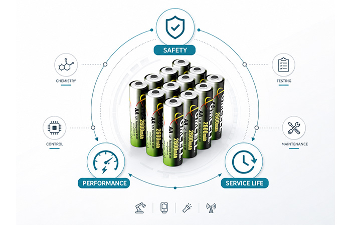
Chemistry Selection Battery Safety Performance Control Lifecycle Engineering
Industrial battery engineering balancing safety, performance, and service life
Industrial battery design coordinates chemistry, system control, mechanical protection, testing, and maintenance to balance safety, usable performance, and service life.

What Is Industrial Battery Engineering?

Industrial battery engineering is the process of designing, integrating, testing, and managing battery systems for equipment that requires predictable power, safe operation, long service intervals, and reliable performance under defined electrical, thermal, mechanical, and environmental conditions.

When you select a battery for industrial equipment, choosing a chemistry and capacity is only the beginning. The battery must work within your device’s voltage range, support its continuous and peak-current demands, fit the available space, tolerate the operating environment, and remain compatible with the charging and maintenance strategy. A battery that looks suitable on a datasheet may still perform poorly when exposed to real startup loads, temperature changes, vibration, long standby periods, or repeated cycling.

A complete industrial battery system may therefore involve cell chemistry, cell format, series and parallel configuration, voltage limits, current capability, charging control, thermal design, protection devices, enclosure construction, monitoring, validation, maintenance planning, and an end-of-life strategy. Engineers must consider these elements together because a change in one area can affect the safety, output, cost, and service life of the entire system.

Cell and Pack Design
Chemistry, cell format, series and parallel configuration, enclosure, wiring, and connectors.
Electrical Performance
Voltage window, capacity, continuous current, peak loads, efficiency, and runtime.
Control and Protection
Charging method, temperature sensing, current limits, fuses, monitoring, and fault response.
Validation and Lifecycle
Testing, manufacturing controls, maintenance intervals, replacement criteria, and end-of-life planning.

Industrial Batteries vs Consumer Batteries

Consumer products often prioritize compact dimensions, low weight, maximum energy density, rapid charging, and product appearance. Their batteries may also be replaced when the device reaches the end of a relatively short commercial lifecycle. Industrial equipment creates a different set of expectations because battery failure can interrupt production, disable monitoring, erase stored data, prevent emergency operation, or increase field-maintenance costs.

C

Consumer Battery Priorities

  • Small size and low weight
  • Maximum energy density
  • Fast charging
  • Product aesthetics
  • Convenient everyday use
  • Shorter replacement cycles
I

Industrial Battery Priorities

  • Predictable voltage and stable output
  • Long-term product availability
  • Harsh-environment tolerance
  • Controlled maintenance
  • Production traceability
  • Safety validation
  • Application compatibility

An industrial battery is not defined only by its chemistry or size. It is defined by how completely the battery system has been engineered around your equipment.

Why Industrial Battery Design Requires Engineering Trade-Offs

When you evaluate an industrial battery, safety, performance, and service life cannot be treated as separate specifications. Every decision involving chemistry, charging, operating limits, cell configuration, thermal design, or protection can improve one objective while placing additional pressure on another. Effective industrial battery engineering therefore focuses on finding the most suitable balance for the way your equipment will actually operate.

The safest battery is not automatically the highest-performing battery, and the battery with the highest rated capacity may not provide the longest service life. Your real target is a battery system that supplies predictable power, remains within safe operating limits, and reaches the required maintenance or replacement interval without creating unnecessary size, weight, cost, or control complexity.

Safety

Battery safety requires protection against overcharge, over-discharge, short circuit, excessive current, thermal abuse, cell reversal, mechanical damage, insulation failure, incorrect charging, and internal cell defects.

Performance

Battery performance includes nominal voltage, operating-voltage range, rated capacity, usable energy, continuous current, peak current, voltage stability, runtime, recharge time, low-temperature output, and standby readiness.

Service Life

Battery service life depends on cycle life, calendar aging, capacity retention, internal-resistance growth, storage conditions, charge acceptance, self-discharge, maintenance intervals, and replacement frequency.

How One Design Decision Changes the Entire Battery System

Fast charging
Faster charging can improve equipment availability and reduce downtime, but it may also increase heat generation, make charge termination more difficult, accelerate battery aging, and require more advanced monitoring and control.
Wider operating window
A wider voltage or state-of-charge window gives your equipment access to more usable energy. However, it may increase discharge depth, reduce the safety margin against overcharge or over-discharge, and accelerate long-term capacity loss.
High energy density
Higher energy density can reduce battery weight and volume, which is valuable in portable or space-constrained equipment. The trade-off may be greater thermal-management demand, more complex protection, and tighter manufacturing-consistency requirements.
Conservative design
Conservative current limits, temperature limits, and charge windows can improve safety and extend service life. They may also reduce usable capacity, increase pack size, and raise the initial cost of the complete system.

You should therefore judge each engineering choice by its effect on the complete application. The correct balance depends on whether your equipment prioritizes long runtime, low weight, high peak power, standby readiness, reduced maintenance, harsh-environment operation, or a longer replacement interval.

Engineering Begins with the Application, Not the Chemistry

You should not begin an industrial battery project by asking whether the equipment needs NiMH, lithium-ion, LiFePO4, or lead-acid. You should begin by defining what the equipment must do, how it consumes power, where it will operate, how it will be charged, and how frequently the battery can be inspected or replaced. Only then can you identify the chemistry and pack architecture that provide the right balance of safety, performance, service life, and cost.

A battery that appears suitable from its voltage and capacity ratings may still fail in your application if it cannot support startup current, tolerate the environmental temperature, fit the available compartment, or remain stable during long standby periods. Effective industrial battery selection therefore starts with a complete application profile rather than a single capacity target.

A device that averages 500 mA may still require a battery capable of supplying several amperes during startup, communication, motor activation, alarm signaling, or emergency operation.

Define the Electrical Load

Your first task is to understand the complete electrical behavior of the equipment. The nominal system voltage is important, but you also need to know the minimum voltage at which the equipment can continue operating and the maximum voltage its electronics can safely accept. These boundaries determine the number of cells, the series configuration, the charger design, and the point at which the battery must disconnect.

Voltage requirements
Nominal system voltage, minimum operating voltage, maximum allowable voltage, and discharge cutoff.
Current requirements
Average current, continuous current, peak current, startup current, and the duration of each peak.
Operating pattern
Duty cycle, startup frequency, communication pulses, motor operation, emergency loads, and idle periods.
Standby consumption
Quiescent current, sleep-mode current, monitoring circuits, communication modules, and charger-related losses.

Selecting a battery only from average current can lead to excessive voltage drop, unexpected resets, poor cold-weather startup, or shortened runtime. Your battery must support both the long-term energy requirement and the short-duration power requirement under the worst expected conditions.

Define the Operating Mode

The role of the battery changes the entire engineering approach. A battery used as the primary power source experiences different stresses from one that remains on standby for months and only operates during a power interruption.

Primary Power
The battery supplies most or all of the device’s operating energy and must support repeated discharge and recharge cycles.
Backup and Standby Power
The battery must remain ready over long periods and deliver reliable power immediately when the main supply fails.
Emergency Power
The battery may be used infrequently, but failure during an emergency may have serious operational or safety consequences.
Intermittent or Continuous Use
Load frequency and rest periods affect heat generation, voltage recovery, usable capacity, and charging opportunity.

You also need to determine whether the battery remains connected to a float or trickle charger. Long-term charging can be useful for standby readiness, but the charger must be designed around the chemistry, temperature, expected service period, and the battery’s ability to tolerate continuous charge input.

Define the Operating Environment

Environmental conditions can change battery behavior even when the electrical load remains the same. You should define the minimum and maximum operating temperature, humidity, vibration, mechanical shock, dust exposure, water exposure, altitude, indoor or outdoor installation, and the location of nearby heat-producing components.

Low temperature may increase internal resistance and reduce usable output, while sustained high temperature can accelerate aging and self-discharge. Vibration, moisture, dust, and shock may require stronger enclosures, reinforced connections, improved sealing, or additional insulation.

Define Mechanical and Maintenance Constraints

Your available battery compartment determines more than the outside dimensions of the pack. Engineers also need to understand maximum weight, mounting direction, connector location, cable length, strain relief, service access, and the replacement method. A technically suitable battery may still be impractical if technicians cannot remove it safely or if the connector is inaccessible after installation.

Before finalizing the design, ask:
  • How frequently can the battery be inspected?
  • Can it be replaced onsite without special tools?
  • Will it remain connected to a charger?
  • Is scheduled maintenance acceptable?
  • Must the battery operate unattended for several years?
  • What failure warning or replacement indicator is required?

Battery chemistry should be selected only after the electrical, thermal, mechanical, environmental, and maintenance requirements of your equipment have been defined.

Battery Chemistry Defines the Available Trade-Offs

Once your application requirements are clear, chemistry selection defines the basic operating boundaries of the battery system. Chemistry influences cell voltage, energy density, current capability, charging control, temperature behavior, self-discharge, protection complexity, maintenance, and expected service life.

No chemistry delivers the highest safety, lowest weight, longest life, simplest charging, lowest cost, and best performance at the same time. Your task is to identify which characteristics are essential for the equipment and which compromises are acceptable.

Nickel-Metal Hydride

Nickel-metal hydride cells provide a nominal voltage of approximately 1.2V per cell and have a long history in rechargeable industrial, medical, security, measurement, and embedded applications. Their moderate energy density is lower than that of many lithium-ion cells, but they offer stable discharge behavior, established charging methods, and a relatively robust chemistry for applications that do not require the smallest possible battery pack.

NiMH cells can be assembled into series packs for equipment requiring higher system voltages. Pack reliability depends on cell matching, charge termination, temperature monitoring, and the way the equipment manages long-term charging. NiMH batteries generally have higher self-discharge than many lithium-ion products, so standby duration and maintenance intervals should be considered during design.

For equipment that values proven rechargeability, stable voltage behavior, manageable safety requirements, and predictable maintenance more than maximum energy density, a properly engineered NiMH Battery can remain a practical industrial power solution.

Common application areas

Industrial controllers, medical equipment, security systems, emergency lighting, backup memory systems, measurement equipment, embedded electronics, and portable industrial devices.

Lithium-Ion and NMC

Conventional lithium-ion and nickel-manganese-cobalt chemistries are often selected when high energy density, lower weight, a higher nominal cell voltage, and reduced pack size are important. These characteristics make them suitable for portable industrial equipment and devices where runtime must be maximized within a limited enclosure. The trade-off is a greater need for precise charge-voltage control, protection against overcharge and over-discharge, thermal monitoring, and cell balancing in series-connected packs.

Lithium Iron Phosphate

Lithium iron phosphate is commonly considered where thermal stability, long-cycle potential, and predictable performance are more important than achieving the highest possible energy density. Its nominal cell voltage is lower than that of many conventional lithium-ion chemistries, which affects series-cell count and charger design.

LiFePO4 is widely evaluated for industrial vehicles, stationary storage, material-handling systems, and larger battery packs that use a BMS. Actual service life depends on cell design, depth of discharge, temperature, charge and discharge rates, cutoff limits, and test conditions. A laboratory cycle figure should not be treated as a guaranteed field-life result.

Lead-Acid

Lead-acid remains a mature and widely understood technology for applications requiring high starting current, relatively low initial cost, and established charging infrastructure. Its main limitations are weight, volume, and the maintenance or ventilation requirements associated with particular designs.

Flooded and sealed lead-acid batteries require different installation and maintenance practices. Prolonged partial-charge operation can affect service life, and equalization is relevant only to applicable designs. Typical uses include forklifts, UPS equipment, telecommunications backup, and fixed standby systems.

Primary Lithium

Primary lithium batteries are designed for applications where recharging is unavailable or impractical. Their very low self-discharge and long standby capability can suit remote industrial equipment, smart meters, monitoring devices, alarms, sensors, and installations that must operate unattended for extended periods.

Industrial Battery Chemistry Comparison

Selection Factor NiMH Lithium-Ion / NMC LiFePO4 Lead-Acid Primary Lithium
Nominal voltage About 1.2V per cell Higher cell voltage Lower than many Li-ion types About 2V per cell Depends on chemistry
Energy density Moderate High Moderate to high Low High for long-duration use
Power capability Good with suitable cells Good to very high Good to very high High starting current Application-dependent
Safety-control complexity Moderate High High in larger packs Moderate Low to moderate
Charging method Current, ΔV, temperature, timer CC/CV with protection Chemistry-specific CC/CV Multi-stage charging Not rechargeable
Self-discharge Moderate to high Generally lower Generally low Moderate Very low
Temperature behavior Robust but charge-sensitive Requires strict limits Thermally stable for Li-ion Charging may need compensation Often selected for wide-temperature use
Cycle-life potential Good with correct charging Application-dependent High potential Strongly affected by DoD Single-use
Maintenance requirements Predictable, charger-dependent Monitoring and BMS-dependent Monitoring required Varies by flooded or sealed type Replacement-focused
Relative pack cost Moderate Moderate to high Moderate to high Often lower initially Depends on cell and service life
Typical suitability Embedded, backup, medical, control Portable, compact, high-runtime devices Vehicles, storage, material handling Forklifts, UPS, fixed backup Remote and unattended equipment

NiMH and Lithium-Ion Solve Different Engineering Problems

NiMH and lithium-ion batteries are not interchangeable technologies. Their voltage architecture, charging behavior, protection requirements, energy density, self-discharge, thermal sensitivity, and maintenance characteristics lead to different engineering decisions.

A useful nimh battery vs lithium ion comparison should evaluate the complete device requirements rather than comparing energy density alone. You need to consider voltage compatibility, charging access, protection complexity, expected runtime, maintenance, operating temperature, product lifecycle, and the consequences of battery failure.

Compare the Voltage Architecture

A NiMH cell provides approximately 1.2V nominal voltage, while a conventional lithium-ion cell operates at a significantly higher nominal voltage. This difference changes the required series-cell count, pack dimensions, charger output, protection architecture, and device input range. Replacing one chemistry with another may require redesigning the electronics rather than simply installing a battery with similar capacity.

Compare the Charging Control

NiMH charging
Charging may use negative delta-V detection, temperature rise, dT/dt, a maximum-temperature limit, and a safety timer. Long-term trickle charging must be evaluated carefully because charge rate and temperature directly affect aging and standby reliability.
Lithium-ion charging
Lithium-ion systems normally use constant-current and constant-voltage charging with strict maximum cell-voltage limits. Charge-current limits, low-temperature charging restrictions, overcharge protection, and BMS control become essential parts of the battery system.

Compare Protection Complexity

Both chemistries may use fuses, thermistors, thermal switches, current monitoring, and pack-level protection. Lithium-ion packs are more likely to require a dedicated protection circuit or BMS that monitors cell voltage, current, temperature, state of charge, and balancing. Many smaller NiMH packs use simpler protection and charger-based monitoring, although the required architecture depends on pack voltage, application risk, and charging method.

NiMH may suit your application when:
  • Safety simplicity is important.
  • An existing 1.2V cell architecture must be retained.
  • Moderate energy density is acceptable.
  • Long-term product support matters.
  • Rechargeable backup power is required.
  • Planned maintenance is acceptable.
Lithium-ion may suit your application when:
  • Weight and size are tightly constrained.
  • Long portable runtime is required.
  • High energy density is essential.
  • The product can support advanced protection.
  • Accurate SOC monitoring is needed.
  • The battery system can support a dedicated BMS.

NiMH vs Lithium-Ion Engineering Comparison

Engineering Factor NiMH Lithium-Ion
Cell voltage About 1.2V nominal Higher nominal voltage
Energy density Moderate High
Weight Higher for equal energy Lower for equal energy
Charging method ΔV, temperature, current, timer CC/CV with voltage control
Protection requirements Often simpler Usually more complex
Overcharge tolerance Relatively more tolerant Requires strict prevention
Self-discharge Generally higher Generally lower
Temperature sensitivity Charging temperature must be monitored Strict charging and operating limits
Maintenance Predictable replacement and charger checks BMS data and protection-system checks
Pack complexity Low to moderate Moderate to high
Typical industrial uses Backup, medical, control, embedded equipment Portable, compact, high-runtime equipment
Replacement compatibility Suitable for existing 1.2V architectures Often requires electrical redesign

The better chemistry is the one that matches your equipment’s voltage, load, charging method, safety architecture, maintenance plan, and expected service life—not simply the chemistry with the highest energy density.

What Is an Industrial Battery System?

An industrial battery system combines cells with the mechanical, electrical, thermal, control, charging, communication, and protection components required to deliver safe and reliable power to your equipment.

The cells store energy, but they do not form a complete system by themselves. To operate safely inside industrial equipment, the cells must be connected, supported, monitored, charged, cooled, protected, and integrated with the device. The final design may be a compact rechargeable pack inside a medical instrument or a large battery installation with modules, contactors, cooling equipment, communications, and service diagnostics.

When you evaluate an industrial battery system, you should therefore look beyond cell capacity. The complete system must support the required voltage, current, runtime, charging method, environmental conditions, maintenance interval, and failure response of your application.

Core Components of an Industrial Battery System

Cells
Cells are the basic energy-storage units. Their chemistry, nominal voltage, capacity, internal resistance, current capability, temperature behavior, and aging characteristics establish the foundation of the entire battery system.
Modules
Modules organize multiple cells into manageable units that are easier to assemble, test, monitor, cool, replace, and scale. Large industrial systems may combine several modules into a higher-voltage pack.
Battery Pack
The pack brings together the cell arrangement, busbars, wiring, enclosure, connectors, sensors, insulation, fuses, thermal switches, and other protection components required for installation in your equipment.
Charging System
The charger determines the charging current, voltage limits, termination method, temperature limits, recharge time, and standby-charging behavior. It must be matched to the cell chemistry, cell count, capacity, and operating environment.
Monitoring and Control
Monitoring may record cell voltage, pack voltage, current, temperature, state of charge, state of health, fault events, and cycle history. The level of monitoring depends on chemistry, pack size, application risk, and maintenance requirements.
Thermal System
Depending on pack size and power level, thermal control may use natural convection, conductive cooling, forced-air cooling, liquid cooling, heating, insulation, or a combination of these methods.
Equipment Interface
The system connects to your equipment through power outputs, charger connections, communication lines, warning signals, fault alarms, service ports, and diagnostic interfaces.

What Does the Battery System Do?

Store Energy Deliver Controlled Power Maintain Voltage Detect Abnormal Conditions Protect Cells Communicate Status Estimate Remaining Energy Record Degradation Support Maintenance

The battery cell stores energy, but the complete battery system determines whether that energy can be delivered safely, predictably, and repeatedly inside your equipment.

How the BMS Balances Safety, Output, and Battery Life

In a lithium-based industrial battery pack, the battery management system acts as a real-time control layer between the cells and your equipment. It continuously measures battery conditions, compares them with programmed operating limits, and decides whether charging or discharging can continue safely.

The BMS does not create additional energy. Its role is to control how much of the battery’s available energy can be used without exposing the cells to unacceptable voltage, current, temperature, or imbalance. By enforcing these limits, the system may sacrifice a small amount of immediate output or usable capacity to protect safety and extend service life.

What a BMS Monitors

  • Individual cell voltage
  • Total pack voltage
  • Charging current
  • Discharging current
  • Cell and pack temperature
  • Insulation status in applicable high-voltage systems
  • Contactor and disconnect status
  • State of charge
  • State of health
  • Fault and event history

What a BMS Controls

  • Charging permission and limits
  • Discharging permission and limits
  • Maximum current
  • Temperature boundaries
  • Contactors and disconnect devices
  • Cooling and heating systems
  • Cell balancing
  • Fault shutdown
  • Warnings and alarms
  • Communication with the equipment

For example, the BMS may reduce charging current when the pack becomes too warm, limit discharge power when the state of charge is low, disconnect the pack when a cell reaches its minimum voltage, or activate cooling when temperature begins to rise. In this way, battery safety, usable power, and battery life are managed dynamically rather than through fixed hardware limits alone.

What Does 80% SOC Mean?

An 80% state of charge means the battery-management algorithm estimates that approximately 80% of the battery’s defined usable charge remains. It does not necessarily mean that 80% of the battery’s theoretical chemical capacity is available.

State of charge, or SOC, is an estimate rather than a quantity that can always be measured directly. The BMS may calculate it from current flow, cell voltage, temperature, battery models, previous charge and discharge history, and calibration data.

SOC accuracy can be affected by temperature, aging, high current, sensor accuracy, voltage hysteresis, chemistry, and the operating limits programmed into the system. An older battery showing 80% SOC may contain less usable energy than a new battery at the same displayed percentage because its total capacity has declined.

State of Health Shows How the Battery Has Aged

State of health, or SOH, describes the condition of the battery compared with a defined new-battery reference. It is not based on one measurement alone. The system may consider remaining capacity, internal resistance, power capability, charge acceptance, self-discharge, temperature behavior, and recorded fault history.

Remaining Capacity
Indicates how much energy the battery can now store compared with its defined new condition.
Internal Resistance
Higher resistance increases voltage drop and heat while reducing peak-power capability.
Charge Acceptance
Shows how effectively the battery can receive and store energy during charging.
Fault and Usage History
High-temperature events, deep discharge, excessive current, imbalance, and abnormal charging may influence the health estimate.

State of Power Defines What the Battery Can Deliver Now

State of power estimates how much power the battery can safely deliver or accept at the present moment. A battery may still show adequate SOC but be unable to supply a demanding peak load because it is cold, aged, highly resistive, or close to a voltage limit. State-of-power calculations help your equipment avoid asking the battery for more current than it can safely provide.

Cell Balancing Protects Usable Pack Capacity

Cells in a series battery pack do not always age at exactly the same rate. Small differences in capacity, resistance, temperature, and self-discharge can cause their voltages to separate over time. The weakest or most charged cell may then reach a protection limit before the rest of the pack, reducing the energy you can use.

Passive Balancing

Passive balancing removes excess energy from higher-voltage cells, usually by dissipating it as heat. It is comparatively simple and widely used in lithium battery systems, but balancing energy is not recovered.

Active Balancing

Active balancing transfers energy between cells or modules. It is more complex, but it may improve usable capacity and energy efficiency in selected high-value or large battery systems.

Balancing can manage small differences that develop during use, but it cannot fully correct poor manufacturing consistency or severely mismatched cells. Proper cell grading and matching remain important before the pack enters service.

Does Every NiMH Battery Pack Need a Lithium-Style BMS?

Not every NiMH battery pack requires a lithium-style BMS. Many NiMH systems rely on charger control, temperature sensing, current limits, fuses, thermal switches, and equipment-level monitoring. The required control architecture depends on pack voltage, application risk, charging method, and system complexity.

NiMH charging is commonly controlled through current, negative delta-V behavior, temperature rise, maximum temperature, and a safety timer. A small backup pack may need only a thermistor, fuse, and correctly designed charger, while a larger or safety-critical system may require individual voltage monitoring, current measurement, data logging, communication, and more advanced fault detection.

You should therefore avoid treating “BMS” as a universal package with identical functions for every chemistry. The appropriate battery control system is the one that manages the actual risks of the chemistry, pack configuration, charger, equipment, and operating environment.

A well-designed BMS does not simply report battery data. It keeps the cells inside a controlled operating envelope so your equipment receives useful power without sacrificing safety or accelerating avoidable aging.

Thermal Management Protects Both Performance and Lifetime

Temperature affects almost every part of battery operation. It changes internal resistance, available energy, charging behavior, peak-power capability, self-discharge, safety margins, and aging speed. A battery may meet its voltage and capacity targets under laboratory conditions but perform very differently inside your equipment when exposed to cold starts, nearby heat sources, restricted airflow, or repeated high-current operation.

Effective battery thermal management is therefore not simply about preventing overheating. It keeps the cells within a temperature range where your equipment can receive predictable power without placing unnecessary stress on the chemistry or shortening the battery’s useful life.

Where Battery Heat Comes From

Battery heat can come from the cells, the electrical connections, the charger, or the equipment surrounding the pack. Internal resistance converts part of the current into heat whenever the battery charges or discharges. As current rises, heat generation can increase rapidly, particularly in aged cells or packs with poor connections.

Electrical heating
Internal resistance, high charging current, high discharge current, peak loads, undersized wiring, and resistive busbar or connector joints.
Abnormal conditions
Overcharge, incorrect charging, cell imbalance, internal defects, excessive current, and failed temperature or voltage control.
Environmental heating
High ambient temperature, sunlight, motors, processors, power electronics, chargers, heaters, and restricted airflow inside the equipment enclosure.

How Low Temperature Changes Battery Performance

At low temperature, electrochemical reactions slow and internal resistance usually rises. Your battery may then show greater voltage drop under load, lower usable capacity, reduced charge acceptance, and less peak-power capability. A pack that operates normally at room temperature may therefore trigger an early low-voltage shutdown during a cold startup or motor pulse.

When your equipment must operate in cold conditions, evaluate the battery at the actual minimum temperature and under the real peak load. Room-temperature capacity alone will not show whether the pack can start, transmit, actuate, or maintain voltage in the field.

How High Temperature Accelerates Aging

Higher temperature can temporarily improve reaction speed and reduce internal resistance under some operating conditions. That apparent performance benefit can be misleading. Prolonged heat generally accelerates chemical aging, increases self-discharge, raises charging risk, and contributes to material degradation. It may also increase differences between cells if part of the pack remains hotter than the rest.

For this reason, the hottest cell may determine the practical life of the complete pack. Your thermal design should reduce both maximum temperature and temperature variation across cells, modules, connectors, and protection components.

Thermal-Management Methods Should Match Pack Scale

Small Industrial Battery Packs

Small packs often control heat through relatively simple mechanical and electrical measures:

  • Natural convection
  • Conductive heat paths
  • Adequate cell spacing
  • Equipment ventilation
  • Correct thermistor placement
  • Heat-resistant insulation and enclosure materials
  • Appropriate charge and discharge-current limits
Medium and Large Battery Systems

Larger packs may require active systems because they contain more cells, store more energy, and can develop significant temperature differences:

  • Forced-air cooling
  • Liquid cooling
  • Battery heating systems
  • Thermal interface materials
  • Module-level temperature sensing
  • HVAC integration
  • BMS-controlled power reduction or shutdown

Thermal Runaway Requires Chemistry-Specific Controls

Thermal runaway is most relevant to battery chemistries and pack designs capable of entering a self-heating failure sequence. Possible triggers can include internal defects, external heating, severe overcharge, short circuit, mechanical damage, or failure of the control system.

Where this risk applies, pack engineering may need to address early detection, electrical isolation, controlled venting, emergency shutdown, cell or module spacing, thermal barriers, and resistance to failure propagation. These measures should be selected according to chemistry, stored energy, installation location, and the consequences of a pack-level event—not copied indiscriminately from a different battery application.

Thermal management must match the battery chemistry, pack size, charge rate, discharge rate, installation environment, and consequences of failure.

Mechanical and Electrical Design Provide Hardware-Level Safety

Software controls and charging algorithms cannot protect a battery from every physical hazard. Your battery pack must also survive vibration, shock, operator handling, electrical faults, dust, moisture, repeated connection cycles, and the mechanical forces created by the equipment itself.

Effective industrial battery safety therefore depends on hardware that keeps cells in position, controls current, maintains insulation, protects terminals, prevents incorrect connection, and preserves reliable electrical contact throughout the intended service life.

Structural Integrity Keeps the Battery Stable

Battery cells and electrical joints should not be allowed to move freely inside the enclosure. Repeated vibration or shock can damage insulation, weaken welds, loosen fasteners, fatigue wires, deform the enclosure, or place stress on cell terminals. These risks are especially important in forklifts, warehouse vehicles, mining equipment, construction machinery, mobile robots, and other equipment exposed to continuous motion.

Vibration Mechanical Shock Drop Compression Puncture Risk Cell Movement Mounting Strength Fastener Retention

The Enclosure Must Protect Without Trapping New Risks

The battery enclosure protects cells and internal connections, but it must also support heat release, pressure management, service access, and installation requirements. Material selection may need to consider flame resistance, impact strength, chemical resistance, thermal expansion, insulation, weight, and long-term dimensional stability.

Environmental protection
Dust resistance, moisture resistance, water exposure, corrosion control, sealing, drainage, and compatibility with indoor or outdoor use.
Pressure and venting
Controlled vent paths, pressure-release features, gas management where applicable, and prevention of pressure buildup inside the enclosure.
Installation and service
Safe lifting, mounting access, connector access, inspection points, replacement procedures, and protection against accidental contact.

Electrical Isolation Prevents Faults from Spreading

Your pack should maintain reliable separation between conductive parts, the enclosure, control circuits, and equipment structures. Insulation barriers, suitable creepage and clearance distances, cable routing, terminal covers, and segregation between high- and low-voltage circuits help prevent short circuits, leakage paths, arcing, and accidental contact.

Connector keying and reverse-polarity prevention are equally important. A connector should not be easy to install in the wrong orientation, confused with an incompatible charger, or pulled loose by cable movement. These apparently small mechanical details can determine whether the battery remains safe during installation and maintenance.

Current Protection Must Match the Real Fault Energy

Fuses, resettable protection, contactors, circuit breakers, and current-limiting devices must be selected according to the pack voltage, expected operating current, peak load, cable size, fault current, and interruption requirements. Protection that is too sensitive may interrupt normal operation, while protection that is too slow may allow damaging heat to build before the circuit opens.

Wire-gauge selection is part of the protection strategy. Undersized wiring increases voltage drop and heat, while oversized wiring can increase weight, cost, and routing difficulty. The correct conductor must support both continuous current and short peak loads under the expected temperature conditions.

Connection Reliability Determines Long-Term Performance

Weld quality, busbar resistance, crimp quality, connector retention, corrosion control, and cable strain relief directly affect voltage stability and heat generation. A weak connection may initially pass a basic functional test but become resistive after vibration, repeated thermal expansion, moisture exposure, or long service. For that reason, connection resistance and mechanical retention should be validated under realistic environmental and load conditions.

Warehouse and Heavy-Equipment Batteries Face Combined Risks

Batteries used in warehouse vehicles, forklifts, construction equipment, and other heavy-duty applications may experience vehicle vibration, repeated shock, high current, long shifts, charging-area hazards, mechanical collision, dust, moisture, and frequent operator handling. These stresses do not occur independently. A loosened connection can create resistance, resistance creates heat, and heat can accelerate degradation or damage surrounding insulation.

Hardware-level safety comes from designing the enclosure, insulation, protection devices, wiring, connectors, and mounting system as one coordinated structure—not as separate components added after the cells have been selected.

Battery Performance Is More Than Rated Capacity

A battery with a higher amp-hour rating does not automatically provide better performance in your equipment. Rated capacity is normally measured under defined laboratory conditions, but your device may operate at a different current, temperature, cutoff voltage, or duty cycle. It may also require short bursts of power that a high-capacity battery cannot deliver without excessive voltage drop.

To evaluate industrial battery performance correctly, you need to consider capacity, usable energy, power capability, voltage stability, internal resistance, efficiency, and the actual load profile together. The most useful battery is the one that keeps your equipment operating reliably—not simply the one with the largest number printed on its label.

Capacity, Energy, and Power Describe Different Things

Capacity — Ah

Amp-hours describe how much electrical charge the battery can deliver under specified conditions. Capacity helps estimate runtime, but it does not show the battery voltage or how quickly that charge can be delivered.

Energy — Wh

Watt-hours combine voltage and capacity to describe stored energy. Two batteries with the same amp-hour rating may contain very different amounts of energy if their voltages are different.

Power — W

Watts describe how quickly energy is delivered. Power capability determines whether the battery can support motors, transmitters, actuators, pumps, alarms, and other demanding loads.

Capacity helps estimate how long the battery may operate, energy describes how much work it can support, and power determines whether it can handle the load at the moment your equipment demands it.

Usable Capacity Depends on Real Operating Conditions

The capacity available to your equipment can be lower than the rated value. A higher discharge rate may increase voltage drop and reduce the point at which the device can continue operating. Low temperature can slow electrochemical reactions, while aging and internal-resistance growth can reduce both runtime and peak-power capability.

Electrical conditions
Discharge rate, continuous current, peak-current duration, cutoff voltage, wiring resistance, and device efficiency.
Battery condition
Cell aging, internal resistance, capacity loss, pack imbalance, self-discharge, and previous operating history.
Environmental conditions
Cell temperature, ambient temperature, airflow, nearby heat sources, cold starts, and temperature variation across the pack.

Voltage Stability Determines Whether Energy Is Actually Usable

Open-circuit voltage is measured when the battery is not supplying a meaningful load. Once your equipment begins drawing current, the terminal voltage falls to the loaded voltage. The difference is influenced by current, temperature, internal resistance, wiring, connectors, and cell condition.

Open-circuit voltage
The voltage measured when the battery is resting with little or no load.
Loaded voltage
The actual battery voltage while your equipment is drawing current.
Voltage sag
The temporary drop caused by current demand and resistance. Excessive sag may trigger shutdown even when energy remains.
Recovery voltage
The voltage rise that occurs after the load decreases or is removed.
Device cutoff
The minimum voltage at which your equipment, protection circuit, or controller stops operation.

Peak Current Can Matter More Than Average Current

Motors, pumps, relays, radio transmitters, medical actuators, emergency alarms, and forklift drive systems may draw current far above their normal operating average. Your battery must maintain sufficient loaded voltage during these events. Otherwise, the device may reset, fail to start, transmit weakly, operate slowly, or shut down.

Peak-current testing should reproduce the real pulse amplitude, duration, frequency, temperature, and battery age. Testing only a fully charged new battery at room temperature may hide performance problems that appear after months of use or during cold operation.

Internal Resistance Connects Power, Heat, and Aging

As battery internal resistance rises, the pack experiences more voltage drop and produces more heat at the same current. This reduces power capability, energy efficiency, runtime, and the amount of capacity your equipment can use before reaching its cutoff voltage.

Resistance trending can also help identify aging. A battery may still retain acceptable capacity during a slow laboratory discharge while becoming unable to support a demanding peak load. For industrial equipment, both remaining capacity and power capability should be considered when setting replacement criteria.

Efficiency Losses Reduce Real Runtime

Coulombic Efficiency
Compares the charge removed during discharge with the charge supplied during charging.
Energy Efficiency
Accounts for both charge and voltage, showing how much input energy is returned during discharge.
System Losses
Include charger loss, wiring loss, connector resistance, control electronics, heat, and standby consumption.

Battery A may have a higher rated capacity, while Battery B may provide more usable energy because it maintains voltage more effectively under your equipment’s real load.

How Engineers Extend Industrial Battery Service Life

Industrial battery life is not determined by chemistry alone. Charging current, discharge current, temperature, depth of discharge, cell matching, storage conditions, charge termination, and maintenance all influence how quickly the battery loses capacity or power capability.

To extend industrial battery service life, engineers reduce avoidable electrical, thermal, and mechanical stress while preserving enough usable energy and power for the application. The correct strategy depends on whether the battery cycles every day, remains on standby, operates in extreme temperatures, or must support short but demanding emergency loads.

Cycle Life and Calendar Life Measure Different Aging Processes

Cycle Life

Cycle life describes how the battery changes through repeated charging and discharging. It is influenced by:

  • Charge rate
  • Discharge rate
  • Depth of discharge
  • Operating temperature
  • Charge termination accuracy
  • Cell matching and pack balance
Calendar Life

Calendar life describes aging that occurs with time, even when the battery is not completing frequent cycles. It is influenced by:

  • Storage temperature
  • Stored state of charge
  • Elapsed time
  • Humidity and environment
  • Self-discharge
  • Natural material degradation

A battery used in daily material-handling equipment may be limited mainly by cycle aging. A standby battery inside an alarm, controller, or backup system may complete few cycles but still age because of time, temperature, self-discharge, and continuous charging.

Depth of Discharge Changes the Stress of Each Cycle

Depth of discharge, or DoD, describes how much of the battery’s available capacity is removed during a cycle. Deeper discharge usually places more stress on the battery during each cycle because a larger portion of the active material is used and the cells move closer to their operating limits.

However, different chemistries respond differently to discharge depth, voltage limits, and partial cycling. You should not apply a universal 20%–80% operating rule to every NiMH, lithium-ion, LiFePO4, or lead-acid system. The suitable window must be based on chemistry, load, required runtime, charger design, temperature, and replacement target.

A Conservative SOC Window Can Preserve Battery Life

Reduced chemical stress
Avoiding extreme charge and discharge conditions may reduce strain on active materials and internal structures.
Preserved reserve capacity
Maintaining a reserve helps the battery support unexpected loads and reduces the risk of reaching a damaging low-voltage condition.
Improved safety margin
Conservative limits provide more tolerance for estimation error, cell imbalance, temperature variation, and aging.
Reduced usable energy
The trade-off is shorter runtime or the need for a larger battery pack to deliver the same usable energy.

Charge Rate Affects Heat, Control, and Aging

Faster charging can reduce downtime, but it also increases heat and places greater demand on charge acceptance, temperature monitoring, and termination accuracy. In NiMH packs, an excessive charge rate or delayed termination can increase temperature and internal pressure. In lithium-based systems, charge current and cell voltage must remain inside tightly controlled limits.

The correct charging rate should reflect the chemistry, cell design, pack size, temperature, available cooling, recharge-time target, and expected service life. A charger designed only to minimize charging time may create unnecessary aging or reduce safety margins.

High Discharge Rates Reduce Usable Performance

High discharge current increases voltage sag and heat generation. It may reduce usable capacity because the device reaches its cutoff voltage earlier, even though energy remains in the cells. Repeated high-rate operation can also accelerate internal-resistance growth and make differences between cells more significant.

When your equipment has demanding peak loads, test the pack after aging and at the lowest operating temperature. A battery that supports the load when new may no longer maintain sufficient voltage after its resistance has increased.

Storage Conditions Continue to Affect the Battery

Batteries continue to age while stored. A moderate and stable temperature generally supports more predictable storage than prolonged exposure to heat. The appropriate storage state of charge depends on chemistry, storage duration, expected self-discharge, and how quickly the battery must return to service.

Your storage plan may include periodic inspection, voltage checks, recharge intervals, self-discharge management, and charger disconnection where continuous connection is not recommended. Long-stored batteries should be verified before being installed in safety-critical or high-demand equipment.

Maintenance Turns Battery Condition into Actionable Data

Physical Inspection
Clean the pack and inspect the enclosure, swelling, leakage, corrosion, mounting, wiring, and connectors.
Electrical Testing
Review capacity, loaded voltage, self-discharge, connection resistance, and internal-resistance trends.
Temperature Review
Check charging temperature, hot spots, sensor placement, airflow, and changes from previous measurements.
Charger Verification
Confirm charge current, voltage limits, termination behavior, standby mode, and temperature controls.
Replacement Planning
Define replacement limits before the battery can no longer support required runtime, peak current, or standby readiness.

Replacement should not be based only on age or remaining capacity. Your criteria should reflect the function the battery must still perform. A pack used for emergency alarms may need replacement when its standby reliability declines, while a motor-driven device may need replacement when resistance prevents acceptable peak-current delivery.

Longer battery life comes from controlling charge, discharge, temperature, storage, matching, and maintenance as one lifecycle strategy—not from relying on a cycle-life number alone.

Cell Matching and Balancing Protect Pack Reliability

A battery pack may contain cells from the same chemistry, format, capacity rating, and production batch, but those cells will never behave with perfect uniformity. Small differences in capacity, resistance, self-discharge, charge acceptance, and temperature response can grow during use. Without proper cell matching and balancing, one weak cell may begin limiting the performance and service life of the entire pack.

This is especially important in series-connected packs. The same current passes through every cell, but each cell may reach full charge or empty discharge at a slightly different time. Your pack is therefore not defined only by its average cell quality. Its usable capacity and safety margin are often determined by the cell that reaches an operating limit first.

What Is Cell Matching?

Cell matching is the process of measuring and grouping cells with similar electrical and thermal characteristics before they are assembled into a battery pack. Matching only by rated capacity is not enough because two cells with similar amp-hour results may still have different resistance, self-discharge, voltage behavior, or charging temperature.

Capacity
Cells should store and deliver similar amounts of charge under the same test conditions.
Voltage
Open-circuit voltage helps identify unusual state-of-charge or self-discharge differences.
Internal Resistance
Resistance affects voltage drop, heat generation, efficiency, and peak-current capability.
Self-Discharge
Cells should lose charge at similar rates during storage and standby periods.
Charge Acceptance
Cells should respond similarly to the selected charging current and termination method.
Discharge Curve
Similar curves help the pack maintain predictable voltage across the operating period.
Temperature Behavior
Uneven heat response can indicate differences in resistance, charging efficiency, or cell condition.

Why the Weakest Cell Matters

If one cell has lower capacity, it may reach empty discharge before the others. In a series pack, continued discharge can then drive that cell into an abnormal low-voltage condition or cell reversal. If another cell has higher resistance or lower charge acceptance, it may become hotter or reach full charge earlier, increasing the risk of localized overcharge.

During charging
One cell may reach full charge first, generate more heat, or experience excessive charge before the rest of the pack is ready.
During discharging
One cell may reach empty discharge first, causing early cutoff, voltage instability, or cell reversal.
At pack level
You may experience reduced usable capacity, uneven temperature, shorter runtime, faster aging, and premature pack failure.

Matching and Balancing Are Not the Same Process

Cell Matching

Matching occurs during cell grading, manufacturing, and pack assembly. Its purpose is to start with cells that behave as similarly as practical before the battery enters service.

Cell Balancing

Balancing occurs during battery use or charging. Its purpose is to manage small differences in voltage or state of charge that develop between cells over time.

Balancing cannot fully compensate for severely mismatched cells. If one cell has much lower capacity, excessive self-discharge, or unusually high resistance, transferring or dissipating small amounts of energy will not restore equal performance.

Matching Priorities Differ Between NiMH and Lithium Packs

In a NiMH battery pack, engineers typically focus on capacity consistency, internal-resistance consistency, self-discharge consistency, and similar temperature behavior during charging. These factors help the charger recognize pack-level charge completion and reduce the chance that one cell overheats or empties earlier than the others.

In a lithium battery pack, the BMS monitors cell-voltage divergence and may use passive or active balancing. Reliable balancing also depends on accurate SOC estimation and appropriate voltage limits. The BMS should detect abnormal divergence, but it should not be expected to conceal poor cell grading, temperature differences, or aging damage.

Battery balancing manages differences that develop during use, while cell matching reduces those differences before the pack enters service.

Charging Strategy Directly Affects Safety and Aging

The charger is not an independent accessory that can be selected after the battery pack has been completed. It determines how quickly energy enters the cells, how charging ends, how temperature is managed, and how the battery behaves during standby. An incorrect charger may reduce available capacity, increase heat, accelerate aging, or create a serious safety risk.

Your battery charging strategy must match the chemistry, cell count, rated capacity, desired charge rate, operating temperature, termination method, protection architecture, and standby behavior. The battery and charger should be developed and validated as one system.

A charger designed for the correct voltage but the wrong chemistry can still be unsafe because different batteries require different current profiles, termination signals, temperature limits, and standby rules.

NiMH Charging Relies on Current, Temperature, and Termination

NiMH cells are commonly charged with controlled current. At practical charging rates, the system may use negative delta-V, temperature rise, dT/dt, a maximum-temperature limit, and a safety timer to determine when charging should stop or reduce to a lower level.

Constant-current charging
Supplies a controlled current selected according to cell capacity, recharge-time target, temperature, and cell design.
Negative delta-V
Detects a small voltage reduction that may occur near full charge, although the signal can be more difficult to identify in some multi-cell packs.
Temperature control
dT/dt and maximum-temperature limits help prevent prolonged charging after cells begin generating additional heat.
Backup termination
A safety timer provides an additional limit if the primary termination signal is delayed, weak, or missed.

Low-rate and trickle charging may be used in selected standby systems, but continuous charge input must remain compatible with the cell design and ambient temperature. In a multi-cell pack, pack-level voltage can hide the behavior of an individual cell, making cell matching and thermistor placement especially important.

Lithium-Ion Charging Requires Precise Voltage Control

Lithium-ion batteries are normally charged using a constant-current and constant-voltage process. The charger supplies controlled current until the pack reaches its defined charge voltage, then holds the voltage while the current falls. Maximum charge voltage, charge-current limits, temperature limits, balancing, and protection cutoff must all match the cell specification.

Charging at very low temperature may need to be restricted because the cells may not safely accept normal charging current. A BMS or protection circuit should detect overvoltage, excessive current, temperature faults, and significant cell imbalance before permitting continued charging.

LiFePO4 Requires Its Own Voltage Profile

LiFePO4 is a lithium-based chemistry, but it does not use the same charge-voltage settings as every other lithium-ion cell. The charging voltage, termination behavior, balancing limits, and BMS configuration must be designed for the specific chemistry and cell manufacturer. A charger intended for a different lithium chemistry should not be assumed compatible.

Lead-Acid Charging Uses Multiple Stages

Bulk Stage
Supplies a substantial portion of the charge using controlled current.
Absorption Stage
Maintains controlled voltage as charging current gradually decreases.
Float Stage
Maintains readiness using a lower voltage suitable for applicable standby systems.
Equalization
Applies only to suitable designs and should follow approved battery and charger procedures.

Lead-acid charging may also require temperature compensation and appropriate ventilation. Flooded and sealed batteries do not necessarily use identical settings, so the charger must match the exact battery design and installation conditions.

How Often Should a Forklift Battery Be Equalized?

Equalization is primarily relevant to applicable flooded lead-acid forklift batteries and should follow the battery and charger manufacturer’s instructions. It should not be treated as a universal maintenance procedure for lithium-ion or NiMH systems.

The required interval depends on battery design, charger settings, operating schedule, water maintenance, temperature, and cell-voltage variation. Unnecessary or excessive equalization may increase heat, water loss, and aging, while inadequate maintenance may allow imbalance or undercharge to persist.

The safest charging strategy is not the fastest or most convenient one. It is the strategy designed specifically for the chemistry, cell count, temperature, usage pattern, and service-life target of your battery system.

Simulation, Digital Twins, and Predictive Battery Monitoring

Industrial battery systems combine electrical, thermal, mechanical, and control behavior. A change in current can increase heat, heat can change resistance, resistance can alter voltage, and voltage can trigger a control response. Simulation helps you study these interactions before committing to final hardware or discovering weaknesses during field operation.

Battery simulation and digital twins can reduce design uncertainty, support component selection, improve sensor placement, and help maintenance teams recognize changes before they lead to downtime. Their value depends on the quality of the underlying model, test data, sensors, and operating records.

Different Models Answer Different Engineering Questions

Electrical Simulation
Predicts voltage drop, current distribution, wiring loss, converter loss, runtime, pack efficiency, and response to startup or peak loads.
Thermal Simulation
Identifies hot spots, temperature gradients, cooling limitations, thermistor locations, airflow paths, and possible thermal propagation.
Mechanical Simulation
Evaluates vibration stress, enclosure deformation, mounting loads, fastener behavior, compression, impact, and collision effects.
Control Simulation
Tests BMS logic, charging algorithms, fault responses, cooling control, contactor behavior, SOC estimation, and shutdown sequences.

Multiphysics platforms can combine these models so that you can study how electrical loading changes temperature, how temperature affects resistance, and how the control system responds. This is particularly useful for larger packs, high-current equipment, constrained enclosures, or systems with active heating and cooling.

A Digital Twin Connects the Model to the Real Battery

A battery digital twin is a digital representation that is updated using information from the operating battery or equipment. Instead of relying only on original design assumptions, the twin can incorporate sensor data and actual usage history.

Battery Model Sensor Data Usage History Temperature History Charge History Maintenance Records

By comparing expected behavior with measured behavior, the model can help you identify deviations. For example, one module may begin heating more than comparable modules, the pack may show greater voltage sag during the same load, or charging may take longer than it did earlier in service.

Predictive Monitoring Looks for Trends, Not Just Alarms

Conventional alarms tell you when a limit has already been reached. Predictive battery monitoring looks for gradual changes that may indicate developing degradation or an emerging fault.

Capacity loss
Runtime or discharge testing shows that the battery stores less usable energy than before.
Resistance increase
Higher resistance produces more voltage sag and heat during the same operating load.
Thermal deviation
One cell, module, connector, or pack location becomes consistently hotter than comparable areas.
Cell-voltage imbalance
Voltage differences increase during charging, discharging, or rest periods.
Abnormal event frequency
Temperature warnings, shutdowns, balancing time, self-discharge, or charge faults begin occurring more often.

Machine Learning Can Support Pattern Recognition

Machine-learning methods may help identify patterns across large fleets, detect unusual behavior, compare similar batteries, or estimate remaining useful life. Their strongest value appears when you have consistent sensor data, verified maintenance records, clear failure definitions, and enough comparable operating history.

These systems should support engineering judgment rather than replace it. A model trained on one chemistry, load profile, climate, or equipment type may not remain accurate when applied to a different battery system. Predictions should be checked against capacity tests, resistance measurements, inspection results, and real equipment behavior.

Simulation and predictive models reduce uncertainty, but they do not replace physical testing under real operating conditions.

Testing and Validation Turn Design Assumptions into Evidence

A battery design can appear reliable in calculations and datasheets but behave very differently once it is installed in your equipment. Real loads, temperature changes, vibration, charging errors, aging, connector resistance, and manufacturing variation can reveal weaknesses that are not visible during initial component selection.

Effective industrial battery testing converts engineering assumptions into measurable evidence. It shows whether the battery can deliver the required runtime and peak power, remain inside safe limits, tolerate the expected environment, and continue meeting your equipment requirements after months or years of use.

Passing a capacity test does not prove that a battery can survive vibration, support a cold startup, tolerate an incorrect charger, or maintain voltage after its internal resistance has increased.

Electrical Testing Establishes the Performance Baseline

Electrical testing confirms how much energy the pack stores, how effectively it delivers that energy, and how it responds to the load profile of your equipment. Capacity and energy tests should be performed under defined current, temperature, cutoff-voltage, and rest conditions so that results remain comparable.

Capacity and energy
Measure amp-hours, watt-hours, discharge duration, capacity retention, and the amount of energy available before the defined cutoff voltage.
Voltage behavior
Record open-circuit voltage, loaded voltage, discharge curve, voltage sag, recovery voltage, and end-of-discharge behavior.
Current capability
Verify continuous current, peak current, startup current, pulse duration, voltage stability, and thermal response under demanding loads.
Aging indicators
Measure internal resistance, charge acceptance, self-discharge, leakage current, and standby current to identify gradual degradation.

Cycle Testing Shows How the Battery Changes with Use

Battery cycle testing should reproduce the way your equipment will charge and discharge the pack. Full cycles may be useful for establishing maximum stress, but many industrial systems operate through partial cycles, irregular duty patterns, or long standby periods. These conditions should also be represented.

Full Cycles Partial Cycles Different DoD Windows Different Charge Rates Different Discharge Rates Capacity Retention Resistance Growth

During cycling, you should track both capacity loss and resistance growth. A battery may still store an acceptable amount of energy while losing the ability to support your equipment’s peak current. Replacement criteria should therefore reflect the real function the battery must perform.

Environmental Testing Reproduces Field Conditions

Environmental tests reveal whether your battery pack remains safe and functional outside controlled laboratory conditions. High- and low-temperature testing evaluates output, charging behavior, resistance, and material stability. Temperature cycling can reveal expansion, contraction, sealing, connection, and insulation problems that do not appear at a constant temperature.

Temperature
High temperature, low temperature, cold start, high-temperature charging, and repeated thermal cycling.
Mechanical Stress
Vibration, mechanical shock, drop, mounting loads, and repeated movement inside the equipment.
Environmental Exposure
Humidity, dust, moisture, condensation, water exposure, corrosion, and enclosure sealing.

Abuse and Safety Testing Examine Failure Conditions

Battery safety validation must include abnormal conditions, not only correct operation. Depending on the chemistry, pack design, application, and applicable requirements, testing may examine overcharge, over-discharge, short circuit, incorrect charging, excessive current, external heating, mechanical damage, and protection-system failure.

The goal is not simply to prove that the battery survives every event unchanged. It is to understand how the pack responds, whether hazards remain controlled, whether protection activates correctly, and whether one failure can spread to other cells, modules, wiring, or equipment.

Pack-Level Testing Verifies the Complete Assembly

Protection functions
Fuse operation, protection cutoff, contactor behavior, thermal switches, alarms, fault shutdown, and recovery logic.
Sensors and communication
Sensor accuracy, SOC data, temperature readings, BMS communication, diagnostic output, alarm signals, and event logging.
Electrical connections
Welding resistance, busbar loss, crimp quality, connector temperature, cable voltage drop, terminal retention, and polarity.
Mechanical construction
Insulation, creepage and clearance, enclosure strength, mounting stability, sealing, strain relief, and service access.

Application Testing Must Use the Real Equipment

A test bench cannot reproduce every interaction between the battery and your equipment. Final validation should therefore include startup, peak load, normal operation, charging, standby, emergency mode, and end-of-discharge behavior in the actual device or a representative system.

You should also verify aged and abnormal conditions. Test high-resistance cells, capacity-mismatched cells, cold starts, high-temperature charging, low state of charge, and charger faults. A design that operates only with perfectly matched new cells may not remain reliable in the field.

Reliable validation asks not only whether the battery works when everything is new and correct, but whether it remains safe and useful when temperature, aging, load, charging, and manufacturing variation move away from ideal conditions.

Battery Safety Must Be Managed Across the Entire Lifecycle

Battery safety does not begin when the pack is installed, and it does not end when the equipment is switched off. Risks can be introduced during chemistry selection, pack design, manufacturing, transportation, installation, charging, operation, maintenance, removal, and recycling.

A strong battery lifecycle safety strategy assigns controls to every stage. This prevents safety from depending on a single fuse, BMS, enclosure, inspection, or operator decision. Each stage should reduce risk before the battery reaches the next one.

Safety Begins During Design

During design, you should identify the electrical, thermal, mechanical, environmental, and human risks associated with the battery. Chemistry selection, voltage, stored energy, charge rate, load current, maintenance access, and the consequences of failure all influence the protection architecture.

Risk Assessment Chemistry Selection Protection Architecture Fault Analysis Thermal Design Charger Compatibility

Fault analysis should ask what happens if a sensor fails, a connector is installed incorrectly, a cell becomes mismatched, the charger exceeds its limit, ventilation is blocked, or the equipment draws more current than expected. The design should control these failures before they create an unacceptable hazard.

Manufacturing Controls Preserve the Intended Safety Design

Even a well-designed battery can become unsafe if production does not reproduce the design consistently. Incoming inspection should verify cells, wiring, connectors, insulation, protection devices, enclosure materials, and other critical components before assembly.

Cell control
Incoming inspection, cell grading, voltage checks, capacity matching, resistance matching, and self-discharge screening.
Process control
Welding parameters, crimp quality, insulation placement, fastener torque, cleanliness, cable routing, and sensor positioning.
Final verification
Traceability, welding inspection, polarity checks, protection testing, sensor checks, communication checks, and end-of-line charging and discharging.

Transportation Requires Its Own Safety Controls

Packaging should prevent movement, crushing, short circuits, terminal contact, moisture exposure, and accidental activation. Documentation, labeling, handling instructions, and state-of-charge requirements should match the battery chemistry, transport method, destination, and applicable rules. Damaged or returned batteries may require different packaging and isolation procedures from new products.

Installation Determines Whether the Battery Enters Service Safely

During installation, verify correct polarity, mechanical mounting, ventilation, cable routing, connector engagement, charger configuration, and clearance from heat sources. The battery should not be installed where cables can be crushed, terminals can be contacted accidentally, or cooling paths can be blocked.

A commissioning test should confirm charging, discharging, communication, alarms, temperature readings, voltage limits, equipment startup, emergency operation, and fault shutdown before the system is released for normal use.

Safe Operation Depends on Monitoring and Discipline

During operation, temperature monitoring, fault alarms, charging discipline, current limits, data logging, and operator training help keep the battery within its intended operating envelope. Repeated warnings should not be cleared without investigation because they may indicate developing resistance, imbalance, poor cooling, charger problems, or connection damage.

Operators should understand correct charging, connector handling, abnormal heat, odor, swelling, leakage, impact damage, and emergency isolation procedures. Clear instructions are especially important in warehouses, industrial vehicles, charging rooms, and multi-shift operations where several people may handle the same equipment.

Maintenance Prevents Small Problems from Becoming Failures

Inspection
Check the enclosure, mounting, wiring, insulation, swelling, leakage, damage, and ventilation.
Cleaning
Remove dust, moisture, corrosion, and conductive contamination using approved procedures.
Electrical Checks
Inspect connectors, measure capacity, review resistance trends, and verify charger behavior.
Replacement Planning
Define limits for runtime, resistance, temperature, fault frequency, damage, and age before failure occurs.

Fault investigation should identify the root cause rather than simply replacing the pack. Otherwise, a charger problem, equipment fault, cooling restriction, incorrect load, or installation issue may damage the replacement battery in the same way.

End-of-Life Batteries Still Require Controlled Handling

At end of life, the battery should be isolated, removed safely, protected against short circuit, stored in an appropriate location, documented, and directed to a suitable recycling or disposal process. Damaged batteries should not be mixed casually with normal returns or general waste.

What Are the Main Safety Aspects of a Battery?

The main safety aspects of a battery are chemistry stability, electrical protection, charging control, thermal management, mechanical protection, monitoring, safe handling, planned maintenance, and controlled end-of-life management. These elements must work together because no single component can control every possible failure.

Battery safety is strongest when risk is reduced at every stage—from chemistry selection and manufacturing to installation, daily operation, maintenance, removal, and recycling.

How Requirements Change by Industrial Application

Industrial applications do not place identical demands on a battery. A forklift may require high current throughout a long shift, while a smart meter may remain unattended for years and draw only occasional communication pulses. A medical device may prioritize traceability and predictable alarms, while a remote infrastructure system may prioritize environmental sealing and solar-charging compatibility.

You should therefore define industrial battery requirements around the real operating profile of the equipment. For every application, determine the load profile, the main safety risk, the factor most likely to limit service life, the chemistry characteristics that matter most, and the testing needed before deployment.

The correct battery is not selected by industry name alone. It is selected by understanding how the equipment draws power, how failure would affect the user, and which operating conditions create the greatest long-term stress.

Electric Forklifts and Warehouse Equipment

Forklifts, automated guided vehicles, pallet trucks, and warehouse robots often operate through long shifts with repeated acceleration, lifting, braking, and opportunity charging. Their battery load profile combines substantial continuous current with short high-current peaks.

High Current Long Shifts Opportunity Charging Fleet Monitoring

The main risks include mechanical shock, connector heating, collision damage, incorrect charging, and high-current faults. Service life may be limited by deep cycling, elevated temperature, repeated fast charging, or poor maintenance. Testing should reproduce full shifts, acceleration peaks, lifting loads, charging-area conditions, vibration, impact, and aged-battery performance. Downtime reduction and predictable replacement planning are often as important as maximum capacity.

Mining and Construction Equipment

Mining and construction systems may combine high peak loads with dust, moisture, vibration, repeated shock, limited service access, and wide temperature variation. A battery installed near engines, hydraulic systems, or exposed metal structures may also face heat and mechanical damage.

Strong enclosures, secure cell retention, sealed connectors, corrosion resistance, and serviceability become essential. Chemistry selection should consider power capability, temperature tolerance, charging access, and fault consequences. Validation should include high- and low-temperature operation, vibration, dust and moisture exposure, peak-current tests, impact resistance, cable retention, and field-replacement procedures.

Stationary Battery Energy Storage

Stationary storage systems are normally designed around long calendar life, scalable architecture, controlled cycling, remote monitoring, thermal management, and fault containment. Because the battery may contain many cells and modules, small differences in temperature or state of charge can become significant at system level.

Important chemistry characteristics include cycle-life potential, thermal stability, balancing requirements, and predictable behavior over years of service. Testing should include module imbalance, cooling failure, sensor faults, communication loss, charge and discharge limits, propagation control, remote shutdown, and degraded-cell operation.

UPS and Backup Power

A UPS or backup battery may remain unused for long periods but must respond immediately when the main supply fails. The load profile is therefore dominated by standby readiness, rapid transition, defined backup duration, and charger compatibility.

Low self-discharge, predictable replacement intervals, stable float or standby charging, and regular capacity verification are critical. Calendar aging, elevated room temperature, hidden charger faults, and infrequent testing often limit service life. Validation should include mains-failure simulation, full backup duration, recharge behavior, long standby periods, aged-battery response, and alarm accuracy.

Industrial Controllers and Embedded Systems

Embedded controllers, PLC-related systems, measurement equipment, and memory-backup circuits often need a compact battery with stable voltage, simple maintenance, long-term availability, and compatibility with an existing electrical architecture.

The battery may supply a small continuous load, retain memory, support real-time clocks, or bridge brief power interruptions. Chemistry characteristics such as rechargeability, self-discharge, voltage behavior, overcharge tolerance, and supply continuity may matter more than maximum energy density. Testing should cover long standby operation, charger behavior, memory retention, device cutoff, temperature, and replacement compatibility.

Medical and Safety-Critical Equipment

Medical and safety-critical equipment requires predictable battery behavior, reliable charging, clear alarms, traceability, controlled manufacturing, and documented maintenance. The consequences of unexpected shutdown may be more important than pack size or energy density.

Testing should include normal use, alarm thresholds, low-battery behavior, charger faults, emergency operation, temperature variation, aged batteries, incorrect installation, and repeated cleaning or handling where applicable. Maintenance documentation should define inspection, capacity checks, replacement criteria, traceability, and actions following damage or abnormal heat.

Smart Meters and Remote IoT Devices

Remote meters and IoT devices frequently operate at very low average current but require brief communication or sensor pulses. The battery may need to remain unattended for years, making self-discharge, pulse-current capability, temperature tolerance, and long-term material stability especially important.

The main service-life risks are storage aging, high-temperature exposure, unexpected communication frequency, and voltage drop during transmission. Testing should reproduce the complete pulse pattern, sleep current, cold transmission, end-of-life resistance, storage time, and worst-case communication schedule.

Smart-City and Remote Infrastructure

Outdoor lighting controls, traffic systems, remote sensors, communications infrastructure, and solar-powered equipment must tolerate changing weather, limited service access, irregular charging, and long periods of unattended operation.

Environmental sealing, remote diagnostics, solar-charging compatibility, low standby consumption, wide-temperature operation, and long maintenance intervals become central requirements. Testing should include solar-input variation, prolonged low-light conditions, water and dust exposure, temperature cycling, communication failure, charger recovery, and long-term standby.

For every industrial application, define the real load, the main hazard, the likely aging mechanism, the chemistry characteristics that matter most, and the tests required to prove the battery can perform in the field.

Manufacturing Consistency Determines Real-World Reliability

A battery design is only valuable if it can be reproduced consistently across production batches. Small variations in cells, welding, insulation, connectors, sensors, wire routing, or assembly pressure can change voltage drop, heat generation, charging behavior, safety response, and service life.

Effective battery manufacturing quality control connects incoming materials, cell grading, pack assembly, process controls, traceability, and end-of-line testing. The goal is not merely to produce a pack that powers on, but to ensure that every approved unit performs within the same defined operating boundaries.

Incoming Materials Establish the Production Baseline

Incoming inspection should verify the materials and components that affect electrical, mechanical, thermal, and safety performance. These may include cells, separators, electrolyte-related materials, metal components, busbars, wires, connectors, insulation, sensors, fuses, thermal switches, and other protection devices.

Cell-related materials
Cell construction, chemistry consistency, separators, electrolyte systems, terminals, casing, and production-batch documentation.
Electrical components
Busbars, wires, connectors, terminals, fuses, protection devices, sensors, circuit boards, and contact materials.
Mechanical materials
Enclosures, holders, insulation sheets, heat-resistant materials, adhesives, fasteners, strain relief, and sealing components.

Cell Grading Reduces Pack-Level Variation

Cells should be graded using characteristics that influence pack behavior. Capacity, open-circuit voltage, internal resistance, self-discharge, charge acceptance, and production-batch consistency help determine which cells can be assembled together.

This process is particularly important for series battery packs because the weakest cell can reach its charging or discharging limit first. Strong cell grading reduces imbalance before use and gives the charger, BMS, and protection system a more consistent pack to manage.

Pack Assembly Converts Components into a Reliable System

Cell Orientation
Correct polarity, spacing, retention, series arrangement, and consistent mechanical support.
Electrical Joining
Welding, busbar design, contact resistance, current paths, and avoidance of damaging heat input.
Insulation and Sensors
Insulation barriers, thermistor placement, thermal switches, voltage sensing, and mechanical protection.
Wiring and Connectors
Correct wire gauge, cable routing, crimp quality, strain relief, connector keying, and polaritying, and control.

Process Controls Keep Production Repeatable

Controlled work instructions should define welding parameters, assembly torque, allowable production temperature, dimensional tolerances, cleanliness, insulation placement, cable routing, sensor position, inspection points, and acceptance limits. A process should not depend entirely on operator judgment when the result affects battery safety or electrical performance.

When working with an industrial battery manufacturer such as GMCELL, engineers should provide complete requirements for voltage, capacity, continuous and peak current, dimensions, charging method, temperature range, connector design, protection components, testing, and target application.

Traceability Helps You Investigate Variation

Traceability links each completed pack to its cell batch, production date, materials, test results, operator or production station, process records, and pack serial number. If a field issue appears, this information helps determine whether the problem is isolated, application-related, or connected to a wider material or process condition.

End-of-Line Testing Confirms the Completed Pack

Electrical checks
Pack voltage, capacity where required, internal resistance, continuity, current capability, and charging and discharging behavior.
Protection checks
Fuse continuity, protection functions, thermal switches, sensor readings, communication, and fault response.
Assembly checks
Connector polarity, cable position, insulation, enclosure closure, dimensions, labeling, serial number, and visible workmanship.

Information Your Battery Supplier Needs

A supplier cannot design a reliable battery from a voltage and capacity request alone. You should provide enough information to reproduce the operating conditions and understand the commercial requirements of the project.

Device Voltage Range Load Curve Battery Compartment Drawing Connector Specification Charger Information Temperature Limits Runtime Target Expected Service Life Compliance Market Annual Demand

Reliable manufacturing is the process of converting one approved battery design into repeatable production units with consistent cells, connections, protection, testing, and traceability.

A Practical Industrial Battery Selection Framework

You can reduce battery-selection risk by following a structured process instead of choosing chemistry, voltage, and capacity independently. The framework below moves from equipment requirements to prototype validation, production control, and maintenance planning.

Each step should produce measurable requirements that can be shared with your engineering team, charger designer, equipment manufacturer, and battery supplier. This gives your industrial battery selection process a clear technical basis.

1
Define the Device Voltage Window

Record nominal voltage, minimum operating voltage, maximum allowable voltage, startup limits, charger limits, and the device cutoff. Do not design from nominal voltage alone.

2
Measure the Real Load Profile

Record average current, continuous current, peak current, startup current, peak duration, duty cycle, standby consumption, and emergency loads.

3
Define Runtime and Recharge Availability

Determine required runtime, charging frequency, available charging time, charger power, standby charging, opportunity charging, and operation during charging.

4
Define Environmental Conditions

Document minimum and maximum temperature, humidity, dust, moisture, water exposure, vibration, shock, altitude, sunlight, and nearby heat sources.

5
Define Mechanical Constraints

Confirm battery-compartment dimensions, maximum weight, mounting direction, connector position, cable length, ventilation, service access, and replacement method.

6
Compare Battery Chemistries

Compare voltage, energy density, power, charging requirements, safety complexity, self-discharge, temperature behavior, service life, maintenance, and cost.

7
Design the Battery and Charger Together

Define charge current, voltage limits, termination, temperature sensing, protection, standby behavior, BMS functions, fuses, alarms, and fault response.

8
Build and Test Prototypes

Complete electrical, thermal, environmental, mechanical, charging, abuse, cycle, and real-equipment tests using both new and aged battery conditions.

9
Define Production and Maintenance Controls

Establish cell grading, assembly controls, traceability, end-of-line testing, inspection intervals, charger checks, capacity limits, fault investigation, and replacement criteria.

The process should remain connected from beginning to end. A change in chemistry may affect the charger, a change in peak current may affect wiring and thermal design, and a change in maintenance access may alter the suitable battery architecture. Review earlier decisions whenever a major requirement changes.

A reliable industrial battery is selected through a documented process that connects equipment requirements, chemistry, charging, protection, validation, manufacturing, and maintenance.

Questions Engineers Should Ask Before Finalizing a Battery System

Before you approve a battery design, confirm that the specification describes the equipment rather than only the battery. A request such as “12V, 5Ah rechargeable pack” does not explain the acceptable voltage range, peak-current demand, operating temperature, charging method, installation space, or expected service life.

Use the following industrial battery design checklist to identify missing requirements before tooling, prototype testing, certification, or mass production begins.

Electrical Requirements
✓ What nominal voltage does the device require?
✓ What is the acceptable operating-voltage range?
✓ What are the continuous and peak-current demands?
✓ How long do startup and peak loads last?
✓ How much runtime is required under the real load?
✓ How will SOC or battery condition be monitored?
Power Role and Charging
✓ Is the battery used for primary, backup, standby, or emergency power?
✓ How frequently can the battery be charged?
✓ How much charging time is available?
✓ Will the battery remain connected to a charger?
✓ Does the charger match the chemistry and cell count?
✓ Is a thermistor, fuse, or thermal switch required?
Environment and Mechanical Integration
✓ What minimum and maximum temperatures must the pack tolerate?
✓ What space is available inside the equipment?
✓ What is the maximum acceptable battery weight?
✓ Must the battery tolerate vibration, shock, dust, or moisture?
✓ Is field replacement required?
✓ Is a custom connector, cable length, or mounting direction required?
Lifecycle, Compliance, and Validation
✓ What cycle life is expected under the defined operating profile?
✓ What calendar life and replacement interval are required?
✓ What transport, market, and equipment requirements apply?
✓ How will production batches be traced?
✓ What defines an unacceptable loss of capacity or power?
✓ How will the battery be tested inside the real device?

If several answers are still unknown, the project is not ready for final battery selection. Resolve the load, charging, environmental, mechanical, lifecycle, and testing requirements before committing to a chemistry or pack configuration. This reduces redesign, improves supplier communication, and gives prototype testing clear acceptance criteria.

A complete battery specification describes how the equipment operates, how the battery is charged, what stresses it must survive, and how reliability will be verified.

Common Engineering Mistakes That Reduce Battery Reliability

Many battery failures begin with a reasonable-looking shortcut: selecting from capacity, reusing an existing charger, relying on a cycle-life figure, or testing only a new prototype. These decisions may reduce development time initially, but they can create voltage instability, overheating, premature aging, maintenance problems, or unexpected equipment shutdown later.

Selecting by capacity alone
Capacity does not describe peak-current capability or voltage stability. Ignoring load current and cutoff voltage can cause early shutdown, inadequate runtime, or equipment resets even when the battery still contains energy.
Assuming maximum energy density is always best
Higher energy density can reduce weight and volume, but it may also require more advanced protection, stricter thermal control, tighter manufacturing consistency, and more complex maintenance.
Using one charger for different chemistries
Different chemistries require different voltage limits, current profiles, termination methods, and temperature rules. An incompatible charger can cause incomplete charging, excessive heat, accelerated aging, or a serious safety fault.
Ignoring peak current
Motors, pumps, radios, actuators, and alarms may demand far more current than their average consumption suggests. An underspecified battery can experience voltage sag, undervoltage shutdown, failed startup, or interrupted operation.
Ignoring cell matching
The weakest cell can reach full charge or empty discharge first. Poor matching reduces usable capacity, creates uneven temperature, increases overcharge or reversal risk, and shortens pack life.
Treating every system as a lithium BMS pack
NiMH, lithium-ion, LiFePO4, and lead-acid batteries use different charging and protection strategies. Applying the same control architecture can add unnecessary complexity or fail to manage the chemistry’s actual risks.
Applying a universal SOC or DoD rule
There is no single operating window suitable for every chemistry and application. A fixed rule may unnecessarily reduce runtime or fail to provide the intended service-life and safety benefits.
Testing only new batteries
New cells usually have lower resistance and stronger capacity. Without aged-cell, cold-start, imbalance, and high-temperature tests, you cannot confirm how the equipment will behave near the end of battery life.
Ignoring connector and cable losses
Undersized cables, poor crimps, worn connectors, and weak welds create voltage drop and heat. These losses reduce efficiency, shorten runtime, and can damage insulation or surrounding components.
Treating laboratory cycle life as field life
Laboratory cycling uses defined temperature, current, cutoff, and rest conditions. Your equipment may experience a different load, charging method, climate, standby pattern, vibration, or maintenance schedule.
Focusing only on purchase price
A lower initial price may be offset by shorter service life, more maintenance, greater downtime, frequent replacements, charger changes, and higher field-service costs.

You can avoid these mistakes by evaluating the complete battery system: the cells, charger, protection, wiring, connectors, enclosure, thermal conditions, equipment load, manufacturing controls, maintenance plan, and replacement criteria. Reliability is usually lost at the interfaces between these elements rather than in one specification alone.

Most battery-design errors come from optimizing one visible specification while overlooking the electrical, thermal, mechanical, charging, or maintenance consequences elsewhere in the system.

Reliable Industrial Batteries Are Engineered as Complete Systems

Battery chemistry establishes the basic capabilities and limitations of the system. It influences voltage, energy density, charging behavior, power capability, thermal sensitivity, self-discharge, protection complexity, and aging. Chemistry alone, however, cannot determine whether the battery will perform reliably inside your equipment.

Electrical architecture, charging control, thermal design, mechanical protection, operating limits, cell matching, monitoring, and fault response determine how safely and effectively that chemistry can be used. Testing then confirms whether the design can support the real load, environment, charging conditions, and expected degradation.

Manufacturing controls, traceability, maintenance, and replacement planning determine whether the approved design can remain consistent throughout production and service. Without these controls, strong laboratory results may not translate into predictable field performance.

The most suitable industrial battery is not necessarily the battery with the highest energy density, highest rated capacity, or longest laboratory cycle life. It is the battery system whose chemistry, electrical architecture, charging method, thermal design, mechanical protection, operating limits, manufacturing controls, and validation process match the real application.

When you treat the battery as part of the complete equipment rather than as an isolated component, you can make clearer trade-offs, reduce development risk, improve safety, and create more predictable performance throughout the intended service life.

Frequently Asked Questions

These answers help you connect industrial battery engineering principles with practical decisions about chemistry, charging, safety, power, service life, testing, and maintenance.

What is industrial battery engineering?

Industrial battery engineering is the process of designing, integrating, testing, manufacturing, and managing battery systems for equipment that requires safe operation, predictable power, controlled maintenance, and reliable performance. It covers cell chemistry, pack architecture, charging, thermal management, protection, monitoring, validation, production controls, maintenance, and end-of-life planning.

How do engineers balance battery safety and performance?

Engineers balance battery safety and performance by selecting an appropriate chemistry, defining safe voltage and state-of-charge windows, limiting charge and discharge current, controlling temperature, and adding suitable electrical and mechanical protection. The goal is to provide enough runtime and power without exposing the cells to excessive heat, overcharge, deep discharge, or damaging current.

What factors determine industrial battery service life?

Industrial battery service life depends on chemistry, temperature, depth of discharge, state-of-charge range, charge rate, discharge rate, charge termination, cell matching, storage conditions, self-discharge, mechanical stress, and maintenance. Calendar aging and cycle aging should both be considered because a standby battery can deteriorate even when it completes relatively few cycles.

What does 80% SOC mean?

An 80% state of charge means the battery-management algorithm estimates that approximately 80% of the battery’s defined usable charge remains. It does not necessarily mean that 80% of the battery’s theoretical chemical capacity is available. Temperature, aging, current, calibration, chemistry, and programmed operating limits can all affect the estimate.

Is a BMS required for every industrial battery?

No. Lithium battery packs commonly require a BMS or dedicated protection circuit to monitor voltage, current, temperature, state of charge, and cell balance. Many smaller NiMH systems instead use charger control, thermistors, fuses, thermal switches, timers, and equipment-level monitoring. Lead-acid systems use their own charging and monitoring methods. The required control architecture depends on chemistry, pack voltage, application risk, and system complexity.

What is the difference between battery capacity and power?

Capacity, measured in amp-hours, describes the amount of electrical charge a battery can deliver under defined conditions. Energy, measured in watt-hours, combines voltage and capacity. Power, measured in watts, describes how quickly the battery can deliver energy. A battery may have high capacity but still be unable to support a demanding motor, pump, transmitter, or actuator if its power capability is insufficient.

Why is cell matching important?

Cell matching groups cells with similar capacity, voltage, internal resistance, self-discharge, charge acceptance, and temperature behavior before pack assembly. In a series pack, the weakest cell may reach full charge or empty discharge first. Poor matching can reduce usable capacity, create uneven heating, increase overcharge or reversal risk, and cause premature pack failure.

How does temperature affect battery performance?

Low temperature generally increases internal resistance, reduces loaded voltage, lowers usable capacity, limits charging acceptance, and weakens peak-power capability. High temperature may temporarily improve output under some conditions, but prolonged heat usually accelerates aging, self-discharge, material degradation, and charging risk. Batteries should be tested at the actual temperature limits of the equipment.

Is lithium-ion always better than NiMH?

No. Lithium-ion is often preferred when low weight, compact size, and high energy density are essential. NiMH may remain suitable when you need a proven rechargeable chemistry, compatibility with an existing 1.2V architecture, manageable protection requirements, stable performance, and predictable maintenance. The correct choice depends on the complete application rather than energy density alone.

How often should a forklift battery be equalized?

Equalization is primarily relevant to applicable flooded lead-acid forklift batteries and should follow the battery and charger manufacturer’s instructions. The appropriate interval depends on battery design, usage, charger settings, temperature, water maintenance, and cell-voltage variation. Equalization should not be treated as a universal procedure for lithium-ion, LiFePO4, sealed lead-acid, or NiMH batteries.

What tests are required for an industrial battery pack?

Testing should normally cover capacity, energy, voltage behavior, internal resistance, continuous and peak current, charging, self-discharge, cycle life, temperature, vibration, shock, humidity, moisture, short circuit, overcharge, over-discharge, protection functions, sensors, connectors, insulation, and enclosure strength. Final validation should also test startup, normal operation, standby, emergency mode, and end-of-discharge behavior in the real equipment.

How can industrial battery life be extended?

Battery life can be extended by using the correct charger, controlling temperature, selecting appropriate charge and discharge rates, avoiding unnecessary operating extremes, matching cells, managing self-discharge, reducing excessive peak loads, and following a planned maintenance schedule. Capacity testing, internal-resistance trending, connector inspection, charger verification, and timely replacement help prevent avoidable field failures.

Reliable battery decisions come from matching chemistry, power, charging, protection, testing, and maintenance to the real conditions of your equipment.