
Why NiMH Batteries Still Matter in Modern Industrial Engineering
When you evaluate a battery for an industrial device, energy density is only one part of the decision. You also need to consider how safely and predictably the battery will perform throughout the equipment’s real operating life.
Lithium-ion batteries dominate smartphones, laptops, electric vehicles, and many modern portable devices because they can store more energy in a smaller and lighter package. However, industrial battery engineering follows a different set of priorities.
For many industrial and embedded devices, the most advanced battery is not automatically the one with the highest energy density. It is the chemistry that best matches your operating environment, charging architecture, safety requirements, maintenance plan, and expected product lifecycle. A properly engineered NiMH Battery can still provide a practical balance of safety, predictable voltage behavior, rechargeability, and long-term availability for industrial equipment.
What you should evaluate beyond energy density
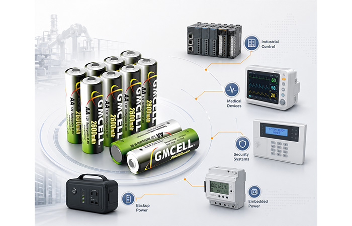
Application-driven6b85c; battery selection
The right industrial battery is defined by your system requirements—not by energy density alone.
NiMH remains relevant where stable performance, mature charging systems, safety tolerance, and long-term replacement availability matter.
What Modern Industrial Battery Engineering Actually Requires
When you select a battery for industrial equipment, the nameplate capacity tells you only part of the story. The more important question is whether the battery can deliver stable, safe, and predictable power throughout the conditions your equipment will actually experience.
Core engineering principle
A reliable industrial battery must match your load profile, operating environment, charging method, maintenance schedule, and expected equipment lifetime—not simply provide the highest possible energy density.
Stable Power Delivery
Your equipment must continue operating when the battery is under load, not only when it is measured at rest. A high nominal capacity provides little value if the voltage falls below the system cutoff as soon as a motor, radio, sensor, or controller demands more current.
Predictable Service Life
Industrial maintenance becomes expensive when battery failure cannot be predicted. You need enough performance data to plan replacement intervals, avoid unplanned downtime, and understand how quickly capacity will decline under your actual charging and discharging pattern.
Safety Under Real Operating Conditions
Laboratory conditions are controlled. Your equipment may not be. A battery system must remain manageable when exposed to temperature changes, electrical abuse, mechanical stress, imperfect charging, and inconsistent field maintenance.
Long-Term Availability
Your industrial equipment may remain in service for five, ten, or more years. The battery therefore needs to be considered as part of a long-term platform, not as a disposable component selected only for the first production run.
What this means for your battery selection
You should evaluate an industrial battery as part of the complete power system. Its chemistry, voltage profile, charging behavior, thermal response, mechanical construction, and future replaceability all influence whether your equipment remains dependable in the field.
Why NiMH Remains Relevant in Industrial Applications
NiMH remains relevant not because it is the newest battery chemistry, but because its operating characteristics still match the requirements of many established industrial systems. When you prioritize safety tolerance, predictable voltage, charging compatibility, and long-term platform support, NiMH can remain a practical engineering choice.
Proven and Stable Chemistry
NiMH has a long history in rechargeable industrial products, embedded equipment, instruments, backup systems, and portable devices. This maturity gives you access to established cell formats, known charging methods, familiar failure behavior, and extensive application experience.
In a properly engineered system, NiMH can provide a relatively tolerant operating platform without requiring the same type of cell-level voltage protection normally associated with lithium-ion packs. This does not mean that NiMH is risk-free. Incorrect charging, excessive heat, short circuits, poor cell matching, or prolonged overcharge can still reduce battery life or create unsafe conditions.
For your design, the advantage is not “absolute safety.” It is a mature and comparatively forgiving chemistry when the cells, charger, protection components, and operating environment are correctly matched.
A Predictable 1.2V Voltage Platform
Many established industrial devices were originally designed around NiCd or NiMH cells. Their charging circuits, voltage thresholds, battery compartments, and power-management logic already expect a 1.2V rechargeable cell platform.
Replacing that platform with a 3.6V or 3.7V lithium-ion cell is not always a direct substitution. You may need to redesign the charging circuit, protection system, voltage regulation, mechanical layout, firmware logic, and product validation process.
Common series pack voltages
By combining cells in series, you can configure a battery pack around the voltage window already supported by your equipment.
Tolerance for Continuous and Trickle Charging
Some backup devices remain connected to a charger for most of their working life. They may experience long standby periods, occasional discharge events, and repeated maintenance charging rather than complete daily charge-and-discharge cycles.
With an appropriate charging design, NiMH can support low-rate trickle charging, timed top-up charging, or maintenance charging. This can make it useful in equipment that must remain ready for an unexpected power interruption.
Control charge current
The maintenance current must match the cell design and temperature conditions.
Monitor heat generation
Prolonged overcharge produces heat and accelerates internal degradation.
Use backup termination
Temperature, voltage, and time limits should work together.
“Trickle-charge compatible” does not mean that the battery can tolerate unlimited overcharge. Your charging method still determines temperature, service life, and long-term capacity retention.
Useful Performance Across Real Operating Temperatures
NiMH has established application experience in many moderate-temperature and selected low-temperature industrial environments. However, you should not assume that every NiMH cell will deliver the same result.
Actual performance depends on the cell formulation, discharge rate, capacity, internal resistance, pack construction, charging temperature, and equipment cutoff voltage. A capacity value measured at room temperature may not represent the energy available inside a cold warehouse, outdoor cabinet, vehicle compartment, or unventilated enclosure.
Evaluate your battery at the actual operating temperature and load profile. Room-temperature capacity alone is not enough to predict field performance.
Easier Integration into Existing Industrial Platforms
Continuing to use NiMH is not necessarily a sign that your equipment is outdated. In many cases, it is a deliberate engineering decision that protects a validated system from unnecessary redesign risk.
The equipment is already validated
Electrical and thermal behavior is already understood.
Certification work is complete
Changing chemistry may affect product safety documentation and approvals.
The charger is already matched
Existing charge control may be unsuitable for another chemistry.
Replacement is straightforward
Compatible packs can preserve field-service procedures and equipment life.
Moving to another chemistry may require changes to the enclosure, charger, protection circuit, firmware, thermal design, testing plan, and certification package. When those changes do not deliver a meaningful system-level benefit, retaining NiMH may be the lower-risk and more economical decision.
Engineering conclusion
NiMH remains relevant when its voltage platform, charging behavior, safety characteristics, and serviceability align with your equipment. Choosing it is not a rejection of newer technology—it is an application-driven decision based on the complete system.
NiMH vs Lithium-Ion: Different Engineering Priorities
When you compare battery chemistries, it is easy to focus on capacity, weight, and physical size. Those specifications matter, but they do not tell you how well a battery will integrate with your charger, protection circuit, operating environment, maintenance process, or existing equipment platform.
A practical nimh battery vs lithium ion comparison should therefore consider more than capacity and weight. You also need to evaluate charging architecture, protection requirements, operating temperature, maintenance conditions, certification impact, and the consequences of battery failure.
Neither chemistry is universally better. The correct choice is the one that delivers the most suitable balance of performance, safety, integration cost, and long-term reliability for your specific device.
The question you should ask
Do you need the highest energy density available, or do you need a battery that fits an established voltage platform, charging method, maintenance model, and validated industrial design?
Engineering Comparison at a Glance
Use these differences as an initial screening guide. Final performance depends on the selected cell, pack construction, charger, load profile, and operating temperature.
| Engineering factor | NiMH | Lithium-ion |
|---|---|---|
| Nominal cell voltage | 1.2V per cell | Typically 3.6V–3.7V per cell |
| Energy density | Moderate | High |
| Protection requirements | Often relatively simple, although pack-level safeguards may still be required | Usually requires dedicated overcharge, overdischarge, overcurrent, and temperature protection |
| Charging tolerance | Can be more tolerant in appropriately designed systems | Requires tighter voltage limits and controlled charging |
| Continuous charging | Maintenance or trickle charging may be possible with correct current and temperature control | Continuous overcharge is generally unsuitable |
| Weight and size | Larger and heavier for the same stored energy | Smaller and lighter for energy-sensitive designs |
| Thermal risk management | Lower thermal-runaway concern, but heat from overcharge and short circuit must still be controlled | Requires careful cell selection, protection, spacing, and thermal design |
| Existing industrial compatibility | Strong where equipment already uses a 1.2V NiCd or NiMH platform | May require charger, protection, firmware, and mechanical redesign |
| Self-discharge | Generally higher, although low-self-discharge variants are available | Usually lower |
| Typical best fit | Backup modules, embedded equipment, mature industrial platforms, and serviceable devices | Portable, high-energy, compact, and weight-sensitive equipment |
Lithium-ion may be the better fit when you need:
NiMH may be the better fit when you need:
Your application should decide the chemistry
Choose lithium-ion when compact size, lower weight, and higher energy density create a meaningful system advantage. Choose NiMH when its voltage platform, charging behavior, serviceability, and compatibility reduce engineering risk. The decision should be based on your complete device—not on one specification.
Industrial Applications Where NiMH Still Makes Sense
NiMH is most valuable when its characteristics solve a defined system requirement. You should consider it for equipment that values stable rechargeable power, predictable maintenance, established charging architecture, and long-term replacement support more than minimum weight or maximum energy density.
Industrial Control and Automation Equipment
In a PLC, CNC controller, automation instrument, or industrial control module, the battery may not power the complete machine. Its role is often to protect the information and functions that must survive a main-power interruption.
Typical battery functions
Parameter retention, memory backup, real-time clock support, control-module power, and short-duration outage protection.
NiMH can make sense when your platform is already validated around a rechargeable low-voltage pack and field replacement must remain straightforward.
Medical and Healthcare Devices
Portable medical equipment, monitoring devices, infusion equipment, diagnostic instruments, and emergency modules may use rechargeable batteries for mobility or backup operation.
The battery and complete device must still be validated against the applicable product requirements. Battery chemistry alone does not establish medical compliance.
Security and Emergency Systems
Security panels, access-control systems, alarm equipment, emergency lighting, and communication backup modules may spend most of their lives connected to external power while remaining ready for an outage.
In these applications, standby readiness, controlled maintenance charging, reliable outage operation, and easy service replacement may be more important than minimum battery weight.
Measurement and Test Equipment
Handheld testers, data loggers, calibration instruments, meters, and industrial measurement tools often need a rechargeable battery that delivers stable performance through repeated field use.
NiMH may be suitable when the device has enough physical space, can be recharged regularly, and already uses a charger designed around the chemistry.
You should still verify peak current, cutoff voltage, runtime, temperature range, and self-discharge against the real measurement cycle.
Embedded and IoT Devices
NiMH is not the automatic choice for every IoT device. A remote sensor expected to operate for years without charging may need a different chemistry. However, NiMH can remain useful in embedded products that meet the right conditions.
Robotics and Specialized Equipment
Cleaning equipment, small robots, industrial remote controls, educational systems, laboratory devices, and specialized mobile equipment may use NiMH where mechanical robustness and established charging are more important than minimum pack size.
Your final choice should reflect the motor-start current, runtime target, charging frequency, pack temperature, available space, and whether users can replace the battery without specialist tools.
Application-fit checkpoint
NiMH makes the most sense when your equipment can accommodate its size, supports appropriate charging, benefits from a mature 1.2V platform, and requires dependable rechargeable power with practical field service.
The Engineering Behind a Reliable NiMH Battery Pack
Choosing NiMH chemistry is only the beginning. The reliability you experience in your equipment also depends on how the cells are selected, matched, connected, protected, and mechanically integrated into the finished battery pack.
A reliable pack must be designed around your voltage range, load profile, charging method, available space, operating temperature, maintenance process, and expected service life. A pack built from individually acceptable cells can still perform poorly if those cells are not properly matched or assembled.
Pack-level reliability
Your battery pack will usually be limited by its weakest cell, highest-resistance connection, poorest thermal location, or least reliable protective component—not by the average specification printed on the datasheet.
Cell Selection Must Start with Your Application
You should not select a cell only because its rated capacity fits your runtime calculation. Two cells with the same nominal capacity can behave very differently under high current, low temperature, repeated charging, or long standby periods.
Capacity
Does the cell provide enough usable runtime at your actual discharge rate?
Discharge rate
Can it support both continuous current and short-duration peaks?
Internal resistance
Will voltage sag remain acceptable when your equipment draws current?
Temperature range
Will the cell charge and discharge reliably in the intended environment?
Cycle life
Does it meet your expected charging frequency and replacement interval?
Charging method
Is the cell compatible with your current, termination logic, and charging time?
Physical format
Can the cell fit the enclosure without creating assembly or cooling problems?
Self-discharge
Will the battery retain enough charge during standby or storage?
Cell Matching Protects the Entire Series Pack
In a series battery pack, the same current flows through every cell. If one cell has lower capacity, higher resistance, or faster self-discharge, it can reach full charge or full discharge before the others.
This imbalance can reduce usable runtime, increase temperature differences, cause premature voltage reversal during deep discharge, and accelerate pack degradation. For that reason, you should evaluate cell consistency rather than average cell performance.
A pack containing eight acceptable but poorly matched cells may be less reliable than a pack containing eight carefully grouped cells with slightly lower individual capacity.
Pack Configuration Determines Voltage and Current Capability
Your cell arrangement must match the electrical requirements of the equipment. Series and parallel connections solve different problems and introduce different balancing and manufacturing challenges.
Series connection
Connecting cells in series increases total pack voltage while the nominal capacity in ampere-hours remains similar to that of one cell.
Example: eight 1.2V cells create a nominal 9.6V NiMH battery pack.
Parallel connection
Connecting parallel branches can increase available capacity and current capability, but current sharing becomes more difficult to control.
Parallel NiMH configurations require careful cell matching, thermal control, wiring symmetry, and charging validation.
Many industrial NiMH packs therefore use a primarily series configuration to reach the required voltage. When additional capacity is needed, you should validate whether a larger cell format is more practical than adding parallel branches.
Connectors and Mechanical Design Affect Field Reliability
Even when the electrical design is correct, your battery can still fail because of an unsuitable connector, excessive wire resistance, weak strain relief, poor insulation, or movement inside the enclosure.
Connector selection
Current rating, contact resistance, locking method, and mating-cycle requirements.
Lead length and wire gauge
Long or undersized leads can create voltage drop and additional heat.
Cell arrangement
The layout must fit the enclosure while supporting assembly and heat dissipation.
Insulation system
Sleeves, barriers, pads, and heat-shrink materials help prevent unintended contact.
Vibration resistance
Cell supports and strain relief reduce movement around welds and wire exits.
Polarity protection
Keyed connectors, clear marking, and physical error-proofing reduce installation mistakes.
Safety Components Should Match the Failure Modes
Your pack may need additional components to limit current, monitor temperature, interrupt charging, protect insulation, or reduce mechanical stress. The correct combination depends on your charging system, maximum fault current, enclosure, and end-use environment.
Adding every possible component does not automatically create a safer pack. Each component must be correctly rated, positioned, tested, and integrated with the equipment’s charging and fault-protection strategy.
What you should confirm before approving a pack design
Confirm the cell model, matching tolerances, series-parallel arrangement, connector, wire gauge, insulation system, thermal sensor location, safety components, mechanical dimensions, polarity, and validation plan. These details determine whether the battery pack will perform consistently after it leaves the test bench.
Charging Engineering Matters More Than Many Buyers Realize
The same NiMH battery pack can deliver very different service life depending on how it is charged. Excessive current, weak termination logic, continuous high-temperature charging, or an unsuitable maintenance-charge strategy can cause heat, capacity loss, imbalance, and premature failure.
Your charger must therefore be treated as part of the battery system. It should control charge current, temperature, termination, backup timing, and post-charge behavior according to the selected cell and pack configuration.
Charge
Apply controlled current
Monitor
Track voltage and temperature
Terminate
Stop at a reliable full-charge signal
Protect
Use time and temperature backup limits
Maintain
Apply an appropriate post-charge strategy
Controlled Constant-Current Charging
NiMH cells are commonly charged using a controlled current. This differs from the constant-current and constant-voltage profile typically associated with lithium-ion charging.
The selected current affects charging time, heat generation, termination sensitivity, and cycle life. A higher current may shorten charging time, but it also demands more accurate monitoring and termination.
Negative Delta V Detection
As a NiMH cell approaches full charge, its terminal voltage may reach a peak and then decline slightly. A charger can use this negative delta V, or −ΔV, signal to determine when charging should stop.
The signal may be subtle, particularly at lower charging currents or under changing temperature conditions. Electrical noise, cell variation, and pack configuration can also make detection more difficult.
Do not rely on −ΔV as the only protection method. Combine it with temperature and time limits.
Temperature-Based Termination
Near full charge, more incoming energy is converted into heat. Monitoring temperature can therefore help your charger identify a full-charge condition or abnormal charging event.
Timer Backup
A maximum charging timer provides a secondary protection layer if the primary voltage or temperature termination method does not operate as expected.
The timer should be calculated from the pack capacity, charge current, expected charge efficiency, starting state of charge, and permitted safety margin. A fixed timer that ignores these conditions may terminate too early or allow excessive overcharge.
Trickle and Maintenance Charging
Some standby systems use a low charging current after the main charge cycle to compensate for self-discharge and keep the battery ready.
This approach can work in selected applications, but the current must remain low enough for the cell to manage the continuous energy input without excessive heat or pressure.
“Suitable for trickle charging” must never be interpreted as “safe for unlimited overcharge at any current.”
Sensor Placement Is Part of the Design
A thermistor can only protect the pack effectively when it measures a representative cell temperature. Poor contact, excessive distance from the cells, or placement near a cooling surface may delay detection.
You should validate temperature measurement across the full pack, especially where central cells may become warmer than cells near the enclosure wall.
Charging Mistakes That Shorten Pack Life
Charging conclusion
A good cell cannot compensate for a poor charger. To protect runtime and cycle life, your charging system should use multiple termination and protection methods rather than relying on one voltage signal.
Temperature, Load, and Real-World Performance
The capacity printed on a datasheet is measured under defined laboratory conditions. Your equipment may operate at a different temperature, draw higher current, use a different cutoff voltage, or experience years of aging.
To estimate real runtime, you need to evaluate temperature, discharge rate, peak current, voltage cutoff, cell age, connection losses, and power-conversion efficiency together.
Low-temperature operation
Cold Conditions Reduce Available Performance
At lower temperatures, electrochemical reactions slow and internal resistance generally increases. Your equipment may therefore see more voltage sag and less usable capacity.
High-temperature operation
Heat Accelerates Aging and Charging Stress
Elevated temperature may temporarily change voltage and discharge behavior, but long-term exposure generally increases self-discharge and accelerates degradation.
Your Load Profile Matters as Much as Capacity
Two devices with the same average power consumption may require different batteries. One may draw a steady low current, while another produces short, repeated peaks when a motor starts, a radio transmits, or a display activates.
Continuous current
The normal current drawn while the equipment is operating.
Peak current
The maximum short-duration current demanded during startup or transmission.
Peak duration
How long the battery must sustain each high-current event.
Standby current
The current consumed while the equipment waits between active events.
Cutoff voltage
The voltage at which your device stops using the remaining battery energy.
Pulse frequency
How often high-current events occur and whether the cell can recover between them.
Runtime reality
Nominal Capacity Is Not the Same as Usable Capacity
Your device can only use the energy delivered before the pack reaches its cutoff voltage. Actual usable capacity may therefore be lower than the rated value, especially under high load, low temperature, advanced cell age, or inefficient power conversion.
Discharge rate
Higher current can increase voltage sag and reduce accessible capacity.
Device cutoff voltage
A higher cutoff may leave part of the battery’s energy unused.
Operating temperature
Cold conditions can increase resistance and reduce practical runtime.
Cell aging
Capacity declines and resistance often rises as the battery ages.
Pack connection losses
Welds, nickel strips, connectors, and wires add resistance.
Conversion efficiency
Regulators, converters, and supporting electronics consume part of the stored energy.
Test the complete system, not only the cell
Validate runtime using the finished battery pack, actual charger, intended device, realistic load pattern, operating-temperature range, and equipment cutoff voltage. This gives you a much more reliable result than calculating runtime from nominal capacity alone.
Testing and Validation for Industrial NiMH Packs
A battery pack should not be approved only because its nominal voltage and capacity match your equipment. You also need evidence that the cells, connections, protection components, charger, and mechanical structure will continue working together under realistic operating conditions.
A useful validation plan moves from incoming cell inspection to electrical testing, environmental stress, cycle-life evaluation, and complete pack-level verification.
Validation principle
You should test the battery under the same voltage limits, charging method, temperature range, load profile, enclosure conditions, and maintenance pattern expected in the final equipment.
Incoming Cell Inspection
Reliable pack production starts before assembly. Incoming inspection helps you identify damaged cells, abnormal electrical values, and inconsistent batches before those cells become part of a finished battery pack.
Visual condition
Check sleeves, terminals, seals, deformation, corrosion, leakage, and transport damage.
Open-circuit voltage
Identify cells that fall outside the accepted voltage window for the batch.
Internal resistance
Screen for cells likely to produce excessive voltage sag or heat under load.
Capacity sampling
Verify that representative cells deliver the expected capacity under defined conditions.
Batch consistency
Compare variation across the lot rather than reviewing only average values.
Charge and Discharge Testing
Electrical testing should show how the pack behaves during normal operation and more demanding conditions. You need to confirm not only total capacity, but also voltage stability, temperature rise, charging response, and performance at the equipment cutoff voltage.
Standard charging
Confirm charge acceptance, temperature behavior, final voltage, and termination performance.
Standard discharging
Verify rated capacity using defined current, temperature, and cutoff conditions.
Fast charging
Evaluate heat generation, termination sensitivity, and recovery after charging.
High-rate discharging
Measure voltage sag, usable capacity, connection losses, and peak temperature.
Temperature-based capacity
Compare runtime and voltage behavior at the expected minimum and maximum temperatures.
Cycle Life Testing Must Reflect Your Use Pattern
Cycle life is not one fixed number that applies to every product. A cell may complete a very different number of useful cycles depending on how deeply it is discharged, how quickly it is charged, how hot it becomes, and what capacity threshold you define as end of life.
For a meaningful result, define the test current, charge method, rest periods, temperature, discharge cutoff, and end-of-life capacity before comparing cycle-life claims.
Environmental Testing
Industrial equipment may experience conditions that are not visible during a room-temperature capacity test. Environmental testing helps you evaluate whether electrical connections, insulation, cell retention, and pack performance remain acceptable after physical and climatic stress.
Pack-Level Validation
Testing individual cells is not enough. Once cells are connected, the pack introduces weld resistance, wire losses, connector interfaces, thermal gradients, insulation boundaries, and protection components that can change real performance.
A test result is only useful when its conditions are clear
When reviewing test data, confirm the cell model, pack configuration, temperature, charge current, discharge current, cutoff voltage, rest time, sample size, and acceptance criteria. Without those conditions, capacity and cycle-life figures can be difficult to apply to your equipment.
Manufacturing Quality Determines Long-Term Reliability
Two battery packs may use the same chemistry, nominal voltage, capacity, and cell size while delivering very different results in the field. The difference often comes from cell consistency, welding quality, electrical resistance, insulation, component selection, assembly control, and production testing.
Battery performance depends not only on chemistry but also on cell consistency, welding quality, insulation, connector assembly, production testing, and batch traceability. Manufacturers such as GMCELL support industrial battery projects by combining cell selection, pack customization, testing, and application-specific engineering.
Manufacturing reality
The finished pack is only as reliable as the consistency of its cells, the resistance of its connections, the integrity of its insulation, and the repeatability of its production process.
Cell Batch Management
Production records should identify the cell model, supplier lot, manufacturing batch, incoming inspection results, storage conditions, and allocation to finished packs.
Capacity and Resistance Matching
Cells should be grouped using defined tolerances so that one weak or high-resistance cell does not limit the complete series pack.
Spot-Welding Quality
Weld energy, electrode condition, weld position, material thickness, and pull strength affect resistance and long-term connection reliability.
Nickel Strip Dimensions
Strip width, thickness, material, current path, and connection length should support the required current without excessive voltage drop or heat.
Insulation Protection
Insulating rings, pads, barriers, sleeves, heat-shrink materials, and cable protection help prevent unintended contact and abrasion.
Harness and Connector Assembly
Crimp height, pull strength, wire gauge, conductor exposure, strain relief, pin position, and connector locking should be controlled.
Polarity Verification
Electrical testing, connector keying, cable color control, labeling, and final inspection reduce the risk of reversed assembly.
Aging and Stabilization
Defined rest or aging periods can help identify abnormal voltage loss, unstable cells, connection problems, or early self-discharge.
Final Capacity Testing
Production sampling or pack-level testing should confirm that finished units meet defined capacity, voltage, and resistance criteria.
Batch Traceability
Pack labels and production records should allow you to trace the cells, materials, operators, test data, and production date.
Packaging and Transportation
Packaging should prevent short circuits, terminal damage, movement, crushing, moisture exposure, and confusion between different pack models.
What a Controlled Production Flow Should Show You
INPUT
Incoming inspection
GROUP
Cell matching
BUILD
Welding and assembly
PROTECT
Insulation and safety parts
VERIFY
Electrical inspection
TRACE
Label and record
SHIP
Protective packaging
Quality conclusion
Using NiMH chemistry does not guarantee a reliable battery pack. Long-term performance depends on whether every cell, weld, strip, wire, connector, insulating part, safety component, and test result is controlled as part of one repeatable manufacturing process.
When NiMH Is Not the Right Choice
NiMH remains useful in many industrial systems, but it should not be selected simply because it is familiar, mature, or comparatively tolerant. Some applications benefit significantly from the higher energy density, lower self-discharge, compact size, or more advanced state monitoring available from other battery systems.
NiMH remains relevant, but it is not universally superior.
Extremely Weight-Sensitive Equipment
When every gram affects portability, flight time, operator fatigue, or mechanical performance, the lower energy density of NiMH may create an unacceptable weight penalty.
Products with Severe Space Constraints
Compact handheld, wearable, miniature, or tightly integrated products may require a thinner or smaller battery format than a NiMH pack can provide.
Applications Requiring Maximum Energy Density
When long runtime must be achieved from the smallest possible battery volume, a suitable lithium-ion system may provide a stronger system-level advantage.
Very Long Storage Without Recharging
Devices that must retain charge for long periods without maintenance may be poorly matched to conventional NiMH because of its generally higher self-discharge.
High-Frequency Deep Cycling
Systems that perform frequent deep cycles and demand very high round-trip efficiency may benefit from another chemistry designed specifically for intensive cycling.
Precise State-of-Charge Estimation
NiMH has a relatively flat discharge-voltage profile, which can make accurate state-of-charge estimation more difficult than in systems using advanced monitoring and characterization.
Equipment Already Designed for Lithium-Ion
If your enclosure, charger, protection circuit, firmware, voltage regulation, thermal design, and certification work already support lithium-ion, moving to NiMH may create unnecessary redesign.
NiMH may still fit
Your priorities are compatibility and serviceability
Consider NiMH when your equipment already supports a 1.2V architecture, uses controlled maintenance charging, has sufficient space, and benefits from a mature rechargeable platform.
Another chemistry may fit better
Your priorities are energy density and compact size
Consider another chemistry when the product must be extremely small, light, energy-dense, efficient, or capable of retaining charge for long periods without maintenance.
Selection conclusion
Do not select NiMH because it is familiar, and do not reject it because lithium-ion is newer. Select the chemistry that best matches your equipment’s voltage, load, temperature, charging, maintenance, safety, size, weight, and lifecycle requirements.
Questions Engineers Should Ask Before Choosing a Battery Pack
Before you compare suppliers or request a battery-pack quotation, define how the battery must operate inside your equipment. A clear set of electrical, thermal, mechanical, charging, maintenance, and compliance requirements will help you avoid selecting a pack that looks suitable on paper but performs poorly in the field.
Use the following checklist to prepare your project specifications. The more accurately you define your voltage window, load profile, charging method, temperature range, available space, safety components, and service-life target, the easier it becomes to design and validate a reliable battery pack.
Start with the complete system
Do not select a battery by capacity alone. Your final pack must work with the device, charger, enclosure, operating environment, maintenance process, and expected product lifecycle.
Electrical requirements
Define How the Battery Must Power Your Device
01 What nominal voltage does the device require?
Confirm the voltage your equipment was designed to receive. For a NiMH pack, each cell contributes approximately 1.2V nominal voltage, so the required pack voltage determines the number of cells connected in series.
02 What is the acceptable operating-voltage range?
Identify the highest voltage your equipment can tolerate and the cutoff voltage at which it stops operating. This range determines how much of the pack’s stored energy your device can actually use.
03 What are the continuous and peak current demands?
Record the normal operating current, maximum peak current, peak duration, and pulse frequency. A battery that supports the average load may still experience excessive voltage sag under short current peaks.
04 How long must the device operate between charges?
Define the required runtime using a realistic duty cycle. Include active operation, standby periods, communication events, motor starts, display use, and any emergency backup interval.
Mechanical and environmental requirements
Confirm Where and How the Pack Will Be Installed
05 How much space is available for the battery pack?
Provide the maximum length, width, height, mounting orientation, cable-exit direction, and clearance around the pack. Include space for insulation, connectors, wires, protective components, and installation access.
06 What is the expected operating-temperature range?
Define charging, discharging, standby, and storage temperatures separately. Battery capacity, internal resistance, charging acceptance, self-discharge, and aging can all change with temperature.
07 Is weight more important than safety tolerance?
Decide whether minimum weight and compact size are essential design priorities. If they are, a higher-energy-density chemistry may be more suitable. If your priorities are a mature platform, serviceability, and charging tolerance, NiMH may remain competitive.
Charging and protection
Define How the Pack Will Be Charged and Protected
08 How will the battery be charged?
Define the charge current, available charging time, power source, termination method, and post-charge behavior. For NiMH, controlled current and reliable voltage, temperature, and timer-based termination are important.
09 Can the system support temperature monitoring?
Confirm whether the charger or controller can read a thermistor or temperature switch. Temperature monitoring can support charge termination, abnormal-heat detection, and charging limits outside the permitted temperature range.
10 Is continuous or maintenance charging required?
If the equipment remains connected to power during standby, define whether the pack needs low-rate trickle charging, periodic top-up charging, or another maintenance strategy. Continuous charging current must be controlled to avoid excessive heat and accelerated aging.
11 Does the device already use a NiMH charging platform?
Review the existing charger, voltage thresholds, firmware logic, thermal monitoring, and battery compartment. Retaining a compatible NiMH pack may reduce redesign and revalidation work in an established industrial product.
12 Does the pack need a thermistor, fuse, PTC, or thermal switch?
Select safety components according to the charger, expected fault current, operating temperature, wire size, enclosure, and equipment requirements. Each component should be correctly rated, positioned, and validated in the completed pack.
Service life and supply continuity
Plan for Maintenance, Replacement, and Long-Term Availability
13 How often can the battery be serviced?
Determine whether the battery is user-replaceable, technician-replaceable, or permanently installed. The cost of access, downtime, labor, and equipment disassembly may be more important than the initial pack price.
14 What cycle life is expected?
Define the expected number of cycles, depth of discharge, charge rate, operating temperature, rest periods, and end-of-life capacity threshold. Cycle-life claims cannot be compared accurately without consistent test conditions.
15 Is a custom connector required?
Specify the connector manufacturer and part number, pin arrangement, polarity, wire gauge, cable length, locking method, and mating connector. A connector that physically fits may still be unsuitable for the required current or service environment.
16 What certification and transportation requirements apply?
Identify the destination markets, end-product category, customer specifications, transportation method, and applicable battery or equipment standards. Required testing and documentation can influence the cell, pack construction, labeling, and packaging.
17 How long must replacement batteries remain available?
Estimate the production life of the equipment and the number of years customers will need replacement packs. Confirm long-term access to compatible cells, connectors, tooling, pack drawings, and production records.
Information to Include in Your Battery-Pack Specification
Final selection checkpoint
The right battery pack should be selected from your complete engineering specification. When voltage, load, charging, temperature, dimensions, protection, maintenance, and supply requirements are clear, cell selection and pack validation become far more reliable.